
n modern industrial automation, the Programmable Logic Controller (PLC) serves as the central “brain” of the control system. It processes complex logic, monitors sensor inputs, and commands output devices to run motors, valves, heaters, and indicators.
However, a PLC output module operates in a harsh electrical environment filled with inductive loads, high inrush currents, and voltage transients. Connecting a PLC output directly to heavy industrial loads can lead to premature hardware failure, fried output cards, and costly plant downtime.
This is where the interposing relay steps in as a vital protective bridge. In this in-depth blog post, we will explore why interposing relays are indispensable for PLC output protection, how they work, and best practices for implementing them in your control panels.
1. Understanding the Vulnerability of Direct PLC Outputs
Most modern PLC output modules use solid-state switching components—such as transistors (sourcing/sinking DC outputs) or Triacs/MOSFETs (for AC outputs)—or miniature electromechanical relays built directly onto the card. While these components are efficient, they have strict electrical limitations:
- Current and Voltage Limits: Standard PLC transistor outputs typically handle low DC voltages (e.g., 24V DC) and limited current per channel (usually 0.5A to 1A). Heavy industrial actuators, solenoid valves, and contactors often draw significantly more current, especially during startup.
- Thermal Stress: Running outputs near or at their maximum threshold continuously generates excessive heat, degrading internal semiconductor junctions.
- Cost of Replacement: A damaged PLC output card often means replacing an expensive module or dealing with lengthy downtime while rewiring terminal blocks.
2. What Is an Interposing Relay?
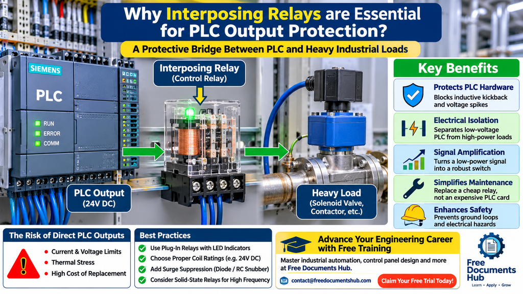
An interposing relay (often referred to as a control relay or auxiliary relay) is an electromechanical relay placed “in between” the PLC output channel and the actual field load.
When the PLC output turns on, it energizes the low-power coil of the interposing relay. The relay’s internal contacts then close, switching the higher voltage or heavier current required to drive the actual field device.
Key Functions:
- Electrical Isolation: Completely isolates the sensitive low-voltage PLC electronics from the noisy, high-voltage field power circuit.
- Signal Amplification: Translates a low-power 24V DC PLC signal into a robust switching action capable of handling heavy AC or DC loads.
- Voltage Level Conversion: Allows a 24V DC PLC output system to control 120V AC, 230V AC, or high-voltage DC loads safely.
3. Core Benefits in Industrial Automation
A. Protecting PLC Hardware from Inductive Kickback
When inductive loads like solenoid valves, motor starters, and electromechanical coils are de-energized, they generate a high-voltage back-EMF (electromotive force) spike—often hundreds of volts.
- Without an interposing relay (or proper suppression diodes), this spike hits the PLC output directly, causing arcing, micro-welding of internal contacts, or semiconductor breakdown.
- With an interposing relay equipped with built-in freewheeling diodes or RC snubbers, the inductive kickback is absorbed by the relay coil circuit, shielding the PLC card.
B. Simplified Troubleshooting and Maintenance
If a field device shorts out or pulls an overcurrent, the interposing relay takes the brunt of the fault.
- Replacing a plug-in electromechanical interposing relay on a DIN rail takes seconds and costs very little.
- Replacing a burnt-out PLC output module requires shutting down the rack, un-wiring terminals, and incurring substantial equipment and labor costs.
C. Enhanced Safety and Galvanic Isolation
Interposing relays provide true galvanic isolation between the control room (PLC low-voltage DC network) and the plant floor (high-voltage AC power distribution). This prevents ground loops, noise propagation, and stray voltage hazards from reaching sensitive controller inputs/outputs.
4. Best Practices for Implementing Interposing Relays
- Choose Plug-In Relays with LED Status Indicators: DIN-rail mounted slim relays with built-in LED indicators make troubleshooting effortless. Maintenance technicians can instantly see whether the PLC output is active and whether the relay coil is energized.
- Select Proper Coil Ratings: Ensure the coil voltage of the interposing relay matches your PLC output rating (e.g., 24V DC standard).
- Incorporate Surge Suppression: For DC inductive loads, ensure flyback diodes are installed; for AC loads, use RC suppressor networks to maximize contact lifespan.
- Account for Switching Frequency: For applications requiring rapid, high-cycle switching (thousands of operations per hour), consider solid-state interposing relays to avoid mechanical wear-and-tear.
Summary
The interposing relay is a small component with a massive impact on system reliability. By acting as a protective buffer between your PLC outputs and heavy field loads, it safeguards expensive hardware, minimizes maintenance headaches, and ensures long-term industrial plant stability.
Advance Your Engineering Career with Free Training
Mastering industrial automation, control panel design, and electrical compliance takes practical, hands-on knowledge. At Free Documents Hub, we provide expert remote training specializing in engineering, design, and technical documentation. Our programs bridge the gap between academic theory and real-world shop-floor execution.
Ready to elevate your technical skills? Contact us today at contact@freedocumentshub.com to claim your free trial and kickstart your learning journey!n modern industrial automation, the Programmable Logic Controller (PLC) serves as the central “brain” of the control system. It processes complex logic, monitors sensor inputs, and commands output devices to run motors, valves, heaters, and indicators.
However, a PLC output module operates in a harsh electrical environment filled with inductive loads, high inrush currents, and voltage transients. Connecting a PLC output directly to heavy industrial loads can lead to premature hardware failure, fried output cards, and costly plant downtime.
This is where the interposing relay steps in as a vital protective bridge. In this in-depth blog post, we will explore why interposing relays are indispensable for PLC output protection, how they work, and best practices for implementing them in your control panels.
1. Understanding the Vulnerability of Direct PLC Outputs
Most modern PLC output modules use solid-state switching components—such as transistors (sourcing/sinking DC outputs) or Triacs/MOSFETs (for AC outputs)—or miniature electromechanical relays built directly onto the card. While these components are efficient, they have strict electrical limitations:
- Current and Voltage Limits: Standard PLC transistor outputs typically handle low DC voltages (e.g., 24V DC) and limited current per channel (usually 0.5A to 1A). Heavy industrial actuators, solenoid valves, and contactors often draw significantly more current, especially during startup.
- Thermal Stress: Running outputs near or at their maximum threshold continuously generates excessive heat, degrading internal semiconductor junctions.
- Cost of Replacement: A damaged PLC output card often means replacing an expensive module or dealing with lengthy downtime while rewiring terminal blocks.
2. What Is an Interposing Relay?
An interposing relay (often referred to as a control relay or auxiliary relay) is an electromechanical relay placed “in between” the PLC output channel and the actual field load.
When the PLC output turns on, it energizes the low-power coil of the interposing relay. The relay’s internal contacts then close, switching the higher voltage or heavier current required to drive the actual field device.
Key Functions:
- Electrical Isolation: Completely isolates the sensitive low-voltage PLC electronics from the noisy, high-voltage field power circuit.
- Signal Amplification: Translates a low-power 24V DC PLC signal into a robust switching action capable of handling heavy AC or DC loads.
- Voltage Level Conversion: Allows a 24V DC PLC output system to control 120V AC, 230V AC, or high-voltage DC loads safely.
3. Core Benefits in Industrial Automation
A. Protecting PLC Hardware from Inductive Kickback
When inductive loads like solenoid valves, motor starters, and electromechanical coils are de-energized, they generate a high-voltage back-EMF (electromotive force) spike—often hundreds of volts.
- Without an interposing relay (or proper suppression diodes), this spike hits the PLC output directly, causing arcing, micro-welding of internal contacts, or semiconductor breakdown.
- With an interposing relay equipped with built-in freewheeling diodes or RC snubbers, the inductive kickback is absorbed by the relay coil circuit, shielding the PLC card.
B. Simplified Troubleshooting and Maintenance
If a field device shorts out or pulls an overcurrent, the interposing relay takes the brunt of the fault.
- Replacing a plug-in electromechanical interposing relay on a DIN rail takes seconds and costs very little.
- Replacing a burnt-out PLC output module requires shutting down the rack, un-wiring terminals, and incurring substantial equipment and labor costs.
C. Enhanced Safety and Galvanic Isolation
Interposing relays provide true galvanic isolation between the control room (PLC low-voltage DC network) and the plant floor (high-voltage AC power distribution). This prevents ground loops, noise propagation, and stray voltage hazards from reaching sensitive controller inputs/outputs.
4. Best Practices for Implementing Interposing Relays
- Choose Plug-In Relays with LED Status Indicators: DIN-rail mounted slim relays with built-in LED indicators make troubleshooting effortless. Maintenance technicians can instantly see whether the PLC output is active and whether the relay coil is energized.
- Select Proper Coil Ratings: Ensure the coil voltage of the interposing relay matches your PLC output rating (e.g., 24V DC standard).
- Incorporate Surge Suppression: For DC inductive loads, ensure flyback diodes are installed; for AC loads, use RC suppressor networks to maximize contact lifespan.
- Account for Switching Frequency: For applications requiring rapid, high-cycle switching (thousands of operations per hour), consider solid-state interposing relays to avoid mechanical wear-and-tear.
Summary
The interposing relay is a small component with a massive impact on system reliability. By acting as a protective buffer between your PLC outputs and heavy field loads, it safeguards expensive hardware, minimizes maintenance headaches, and ensures long-term industrial plant stability.
Advance Your Engineering Career with Free Training
Mastering industrial automation, control panel design, and electrical compliance takes practical, hands-on knowledge. At Free Documents Hub, we provide expert remote training specializing in engineering, design, and technical documentation. Our programs bridge the gap between academic theory and real-world shop-floor execution.
Ready to elevate your technical skills? Contact us today at contact@freedocumentshub.com to claim your free trial and kickstart your learning journey!