
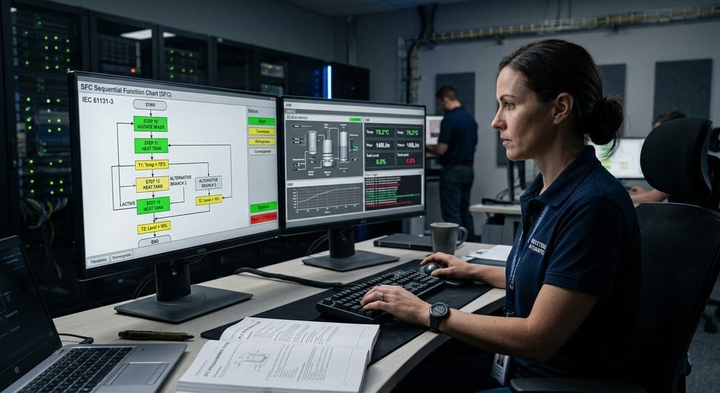
In the world of industrial automation, managing complex, time-sequenced operations—such as chemical batching, automated packaging lines, or multi-stage material handling—can quickly become a nightmare when programmed using traditional, unstructured relay logic. Trying to track hundreds of interlocking bits, latches, and timers across sprawling ladder diagrams often leads to debugging gridlocks and hazardous timing bugs.
To solve this, the international standard IEC 61131-3 introduced Sequential Function Chart (SFC). Based on Grafcet principles, SFC provides a powerful, graphical, state-machine-driven approach to PLC programming.
In this comprehensive guide, we will explore how SFC programming transforms complex batch processes, how state machines operate, and how you can apply best practices to build robust, audit-ready industrial control logic.
1. Understanding the Core Anatomy of SFC Programming
Sequential Function Chart is a graphical programming language that breaks down a complex automation process into manageable, sequential chunks called Steps, connected by directional Transitions controlled by Actions.
A. Steps
A step represents a specific state or phase of a machine or batch process (e.g., Step 1: Fill Tank, Step 2: Heat Mixture, Step 3: Stir, Step 4: Drain). Each step can be active or inactive. When a step is active, the associated actions inside that step are executed continuously or triggered upon entry/exit.
B. Transitions
Transitions represent the logical conditions required to move from one step to the next. A transition is always placed between two horizontal lines intersecting the vertical flow path. It evaluates a boolean condition (e.g., Tank_Level >= 100.0 or Timer_Done.Q). When the condition becomes true, the previous step deactivates, and the subsequent step activates instantly.
C. Actions
Actions are the actual control commands executed when a step is active. They can be written in Ladder Logic (LD), Structured Text (ST), or Function Block Blocks (FBD). Common action qualifiers include:
- N (Non-stored): Executes as long as the step is active.
- S (Set / Latched): Turns on an output and keeps it on even after the step deactivates until explicitly reset.
- P (Pulse): Executes the action for exactly one scan cycle when the step becomes active.
2. Why SFC is the Ultimate Choice for Batch Processes
Batch manufacturing processes—common in pharmaceuticals, food and beverage production, and specialty chemical synthesis—require exact recipes, strict timing sequences, and repeatable phase transitions. SFC shines in these environments for several vital reasons:
Intuitive Process Visualization
Batch processes are inherently sequential. Operators, process engineers, and maintenance technicians can look at an SFC flowchart and instantly understand what phase a reactor vessel or mixing tank is currently in, without having to trace hundreds of lines of code across multiple rungs.
Built-In State Machine Management
In traditional programming, building a state machine requires managing integer states (State = 10, State = 20) alongside complex CASE or IF-ELSE statements. SFC handles state transitions natively at the firmware level of the PLC, eliminating entire classes of logic errors and race conditions.
Effortless Parallel and Alternative Branching
Complex industrial systems often need to execute multiple operations simultaneously or choose paths based on sensor inputs. SFC supports two primary branching structures:
- Alternative Branching (OR Divergence): The program evaluates mutually exclusive conditions and chooses one execution path over another (e.g., choosing a “Wash Cycle A” or “Wash Cycle B” based on recipe selection).
- Parallel Branching (AND Divergence): The program splits into multiple simultaneous execution threads (e.g., opening a nitrogen purge valve while simultaneously starting a vacuum pump). Both branches must complete before the chart converges back to a single path.
3. Comparative Matrix: SFC vs. Ladder Logic vs. Structured Text
| Feature / Criteria | Sequential Function Chart (SFC) | Ladder Diagram (LD) | Structured Text (ST) |
| Primary Strength | Step-by-step sequences, batch processes, state machines | Discrete interlocks, safety rungs, basic start/stop logic | Complex math, arrays, data manipulation, algorithms |
| Readability | Extremely high for sequential workflows | High for electricians; cluttered for large sequences | High for software engineers; low for casual troubleshooting |
| Debugging | Visual step-highlighting shows active states in real-time | Power-rail monitoring on active rungs | Variable watch tables and online value inspection |
| Structural Design | Flowchart-based state machine architecture | Relay schematic layout | High-level textual programming syntax |
4. Best Practices for Developing Robust SFC Control Logic
To ensure your SFC programs remain maintainable, safe, and easy to troubleshoot on the shop floor, follow these proven engineering guidelines:
- Keep Step Actions Modular: Avoid writing massive blocks of code directly inside an SFC step. Instead, call external Function Blocks (FBs) or Structured Text routines from within the step action.
- Implement Timeout Transitions: Always include safety timeout transitions on critical steps (e.g., if
Fill_Valveis open butHigh_Level_Sensordoes not trigger within 60 seconds, transition automatically to an error/alarm state). - Handle Faults and E-Stops Cleanly: Design an overarching reset and emergency stop routine that can force the SFC back to a safe initial state (
Init_Step) without leaving valves open or motors running. - Use Clear Tag Naming Conventions: Adopt structured naming conventions for steps (
S10_Fill_Reactor) and transitions (T10_Tank_Full) to make online monitoring intuitive for commissioning engineers.
Conclusion
Sequential Function Chart (SFC) programming bridges the gap between high-level process design and low-level PLC execution. By structuring complex batch processes and state machines into clear, visual steps and transitions, automation engineers can eliminate debugging headaches, improve plant safety, and deliver clean, maintainable control systems.
🎓 Elevate Your Engineering Capabilities with Free Documents Hub
Mastering industrial programming standards, automation architectures, and plant documentation takes hands-on guidance. At Free Documents Hub, we offer expert remote training specializing in industrial engineering design, PLC programming workflows, and quality control.
🛠️ Access Our Digital Libraries:
- Gumroad Store: https://iftakhar.gumroad.com/
- Payhip Store: https://payhip.com/b/pLP7W
📩 Ready to upgrade your facility’s operational documentation or claim a FREE trial sample? Email us today at contact@freedocumentshub.com!