
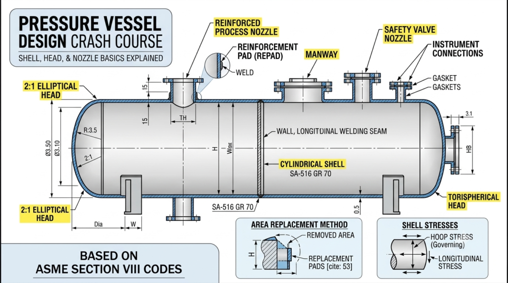
In the world of oil and gas, chemical processing, power generation, and manufacturing, pressure vessels are the unsung workhorses. These robust containers hold gases or liquids at pressures substantially different from the ambient air pressure. Because a structural failure can lead to catastrophic consequences, mastering pressure vessel design basics is one of the most critical milestones for any mechanical, process, or piping engineer.
Whether you are a student, a young engineer, or a seasoned professional looking for a quick refresher, this crash course breaks down the core structural components of a pressure vessel—the shell, the head, and the nozzles—and explains how they function according to industry standards like the ASME Section VIII code.
1. Introduction to Pressure Vessel Codes and Standards
Before diving into individual components, we must establish the rules of the game. You cannot design a pressure vessel based purely on intuition. The industry relies on strict regulatory frameworks to ensure public and operational safety.
The global gold standard for pressure vessel design is the ASME Boiler and Pressure Vessel Code (BPVC) Section VIII. This section is divided into three divisions:
- Division 1: Covers the standard, time-tested design-by-formula approach. It is the most widely used and applies to pressures up to 3,000 psi (approx. 20 MPa).
- Division 2: Utilizes an alternative design-by-analysis approach, allowing for higher design stresses and thinner walls, usually requiring finite element analysis (FEA).
- Division 3: Dedicated to ultra-high-pressure vessels (exceeding 10,000 psi).
For the sake of this crash course, we will focus primarily on the foundational principles aligned with ASME Section VIII Division 1.
2. The Core Backbone: The Vessel Shell
The shell is the primary containment component that forms the main body of the pressure vessel. It is essentially the walls of the tank that wrap around the internal volume.
Types of Shells
Shells generally fall into two primary geometries:
- Cylindrical Shells: By far the most common type due to ease of manufacturing and efficient use of space. Sheets of steel are rolled into cylinders and welded along a longitudinal seam.
- Spherical Shells: The most structurally efficient shape. A sphere distributes internal pressure equally in all directions, allowing for walls that are roughly half as thick as a cylindrical vessel of the same diameter and pressure. However, they are incredibly expensive and difficult to manufacture, making them rare except for massive LPG or LNG storage tanks.
Engineering Calculations for Cylindrical Shells
When an engineer calculates the required thickness of a cylindrical shell under internal pressure, they must account for two types of stresses: hoop stress (circumferential stress acting along the length) and longitudinal stress (acting along the longitudinal axis).
Because hoop stress is twice as high as longitudinal stress, it always governs the minimum required thickness. Under ASME Section VIII Div 1, the basic formula for the thickness ($t$) of a cylindrical shell under internal pressure ($P$) is:
$$t = \frac{P \cdot R}{S \cdot E – 0.6 \cdot P} + CA$$
Where:
- $P$ = Internal design pressure
- $R$ = Inside radius of the shell
- $S$ = Maximum allowable stress value of the material at design temperature
- $E$ = Joint efficiency (a factor based on the level of radiographic testing on the welds, ranging from 0.70 to 1.0)
- $CA$ = Corrosion Allowance (extra material added to ensure the vessel lasts its entire lifespan despite internal rusting or erosion)
3. Capping it Off: Types of Vessel Heads
A shell cannot hold pressure without being enclosed at both ends. These end caps are called heads (or end closures). The geometric shape of the head significantly dictates its cost, weight, and ability to handle pressure.
| Head Type | Geometry & Characteristics | Relative Cost | Pressure Suitability |
| Hemispherical | Half of a perfect sphere. Strongest shape; thinnest wall required. | Very High | Excellent (High-pressure applications) |
| Elliptical (2:1) | A semi-elliptical shape where the major axis is twice the depth. | Moderate | Good (Industry standard for process vessels) |
| Torispherical | Features a dish with a specific crown radius and a curved knuckle radius. | Low | Moderate (Low-to-medium pressure) |
| Flat Head | A completely flat circular plate welded or bolted to the shell. | Lowest | Poor (Requires extreme thickness; used for covers) |
Why Geometric Choice Matters
- Hemispherical Heads: Because they distribute stress beautifully, they require half the thickness of a cylindrical shell. However, because they are formed using deep-drawing processes or multiple welded segments, they are highly labor-intensive to manufacture.
- 2:1 Elliptical Heads: This is the practical “sweet spot” for mechanical engineers. It provides a phenomenal balance of high pressure resistance and manufacturing affordability. Its required thickness is roughly equal to that of a seamless cylindrical shell of the same diameter.
- Torispherical Heads: Often referred to as “klöpperboden” or standard flanged and dished heads. They are cheap to form but experience higher localized stresses at the “knuckle” (the curve joining the dish to the cylinder), meaning they must be designed thicker than elliptical heads.
4. The Gateways: Nozzles and Openings
A pressure vessel is useless if you cannot get fluids into or out of it. Nozzles are cylindrical components that penetrate the shell or head to provide connection points for process piping, instruments, safety valves, and manways (for internal inspection maintenance).
The Challenge of Openings: Stress Concentration
When you drill or cut a hole into a pressure vessel shell to install a nozzle, you break the continuity of the metal. Think of a stretched rubber band—if you poke a hole in it, the stress concentrates tightly around the edges of that hole, inviting a tear.
In engineering terms, this is called stress concentration. To prevent the vessel from rupturing at the nozzle junction, engineers must perform reinforcement calculations.
The Area Replacement Method
ASME Section VIII utilizes a principle known as the Area Replacement Method to ensure nozzle structural integrity.
The Rule of Thumb: The cross-sectional area of metal removed by creating the opening must be fully replaced by excess metal available in the immediate vicinity of the opening.
This “replacement metal” can come from three sources:
- The Shell Thickness: If the actual shell used is thicker than the minimum required by the formula, the excess thickness counts as reinforcement.
- The Nozzle Neck Thickness: If the pipe wall used for the nozzle is thicker than required to contain its own internal pressure, that excess metal contributes to the reinforcement.
- Reinforcement Pads (Repads): If sources 1 and 2 are insufficient, a donut-shaped plate of steel (a repad) is welded around the outside of the nozzle to add the necessary structural area.
5. Critical Design Considerations Beyond the Basics
While shells, heads, and nozzles form the primary pressure boundary, a complete design requires evaluating real-world environmental and operational variables:
- Design Temperature: As metals heat up, their structural strength decreases dramatically. Material allowable stress ($S$) must always be evaluated at the maximum coincident temperature.
- Wind and Seismic Loads: Tall vertical vessels (like distillation columns) act like giant sails. Designers must calculate bending moments caused by wind and earthquakes, often requiring thicker lower shells or heavy anchor-bolted support skirts.
- External Pressure (Vacuum Conditions): If a vessel is suddenly emptied without proper venting, or if steam inside condenses rapidly, it can experience an internal vacuum. Designing for external pressure is entirely different from internal pressure—it becomes a failure mode of buckling rather than bursting, requiring stiffening rings to be welded along the shell.
Summary: Putting It All Together
Mastering pressure vessel design basics requires visualizing how these three primary elements interact under immense structural load:
- The shell acts as the primary containment cylinder, experiencing twice as much hoop stress as longitudinal stress.
- The head safely seals the ends, with its geometry (hemispherical, elliptical, or torispherical) heavily dictating both material weight and fabrication costs.
- The nozzles serve as vital connection points, requiring careful area-reinforcement analysis to compensate for the metal cut away during installation.
By adhering to rigorous standards like ASME Section VIII, engineers ensure that these massive, pressurized giants operate safely and efficiently day in and day out across the globe.
Advance Your Engineering Career with Free Training
Mastering the complexities of ASME codes, reinforcement calculations, and structural documentation takes time, but you do not have to learn it alone.
At Free Documents Hub, we provide expert remote training specializing in all types of engineering, design, and technical documentation. Whether you are looking to master pressure vessel design formulas, perfect your fabrication blueprints, or understand compliance standards, our remote programs are built to bridge the gap between theory and real-world application.
Ready to elevate your technical skills? Contact us today at contact@freedocumentshub.com to claim your free trial and kickstart your training journey!