
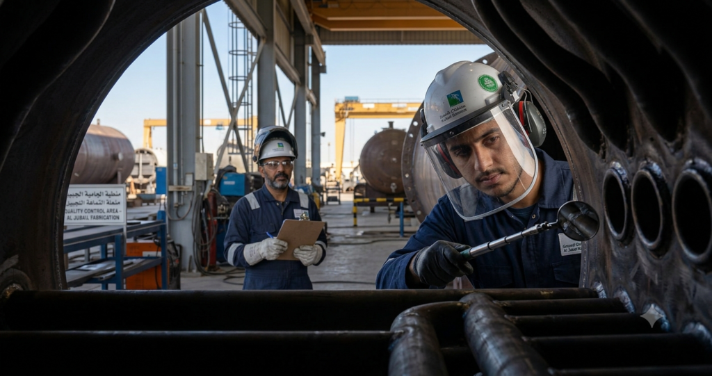
In the fabrication, maintenance, and structural integrity assessment of pressure vessels, piping, and critical industrial equipment, ensuring that a component is free of defects without causing physical damage is a fundamental engineering requirement.
While construction codes like ASME Section VIII dictate the necessary design formulas, geometric constraints, allowable stresses, and manufacturing rules for pressure boundaries, ASME Section V serves as the dedicated international standard for Non-Destructive Examination (NDE).
If you are an engineer, a quality assurance inspector, or a welding professional, understanding how ASME Section V organizes, structures, and mandates NDE methods is crucial for achieving full code compliance, satisfying client specifications, and guaranteeing long-term operational safety.
1. The Core Philosophy and Structure of ASME Section V
To effectively utilize ASME Section V, you must first understand its unique role within the broader ASME Boiler and Pressure Vessel Code (BPVC) ecosystem.
A Reference Standard, Not a Mandate
Unlike Section VIII or Section I, ASME Section V is classified strictly as a reference code. It does not possess the authority to dictate when an inspection must take place, nor does it define the final acceptance or rejection criteria for a particular flaw.
Instead, those decisions are entirely governed by the specific construction code or project specification being followed.
For example, if you are manufacturing a pressure vessel, ASME Section VIII Division 1 will mandate whether a longitudinal weld seam requires full radiography, spot radiography, or no radiography at all based on joint efficiency. Once Section VIII establishes that radiography is mandatory, it points the engineer to ASME Section V, Article 2, which provides the strict, step-by-step technical recipe on how to execute that radiographic test. Once the test is complete, you return to Section VIII to determine if the detected indications are acceptable or require repair.
Structural Breakdown of the Code Book
The entire volume of ASME Section V is systematically organized into two primary subsections that balance field testing protocols with rigorous material science specifications:
- Subsection A — NDE Methods: This subsection consists of individual, standalone Articles. Each Article details the specific requirements, methodology, environmental variables, and equipment setups necessary for a distinct examination technique (e.g., Radiography, Ultrasonics, Liquid Penetrant).
- Subsection B — Subpart Standards: This subsection contains adopted ASTM (American Society for Testing and Materials) standards. These standards offer deep technical specifications regarding the chemical composition of penetrants, the acoustic properties of ultrasonic transducers, and the highly precise calibration protocols for testing machinery.
2. Comprehensive Breakdown of Core NDE Methods (Subsection A)
Section V separates each major non-destructive testing methodology into its own distinct Article to prevent procedural confusion. Below is an exhaustive look at the most heavily utilized articles in heavy industrial manufacturing and pressure equipment fabrication:
+--------------------------------------------------------------+
|                     ASME SECTION V                           |
+------------------------------+-------------------------------+
                               |
        +----------------------+----------------------+
        |                                             |
  SUBSECTION A: NDE Methods             SUBSECTION B: ASTM Standards
  - Article 2: Radiography (RT)         - Material Specifications
  - Article 4: Ultrasonics (UT)         - Equipment Calibration
  - Article 6: Penetrants (PT)          - Chemical Standards
  - Article 7: Magnetic Particle (MT)
Article 2: Radiographic Examination (RT)
Radiography is a volumetric NDE method that employs short-wavelength electromagnetic radiation (either X-rays generated electrically or Gamma rays emitted by radioactive isotopes like Iridium-192 or Cobalt-60) to penetrate a material and capture its internal profile on a digital sensor or film.
- Key Procedural Requirements: Article 2 places immense emphasis on radiographic density, geometric unsharpness, and image quality. To prove that a radiograph has the clarity required to detect tiny cracks or slag inclusions, operators must use IQIs (Image Quality Indicators), colloquially known as “wire gauges” or “hole pens”. These IQIs must be placed precisely according to the code rules, and their designated essential wires must be clearly visible on the processed film.
- Industrial Application: RT is primarily utilized to inspect full-penetration longitudinal and circumferential butt-welds along the main shells and heads of pressure vessels and high-energy piping systems. It provides a permanent, verifiable visual archive of the weld’s internal state.
Article 4: Ultrasonic Examination (UT)
Ultrasonic testing is another volumetric technique, but instead of radiation, it transmits high-frequency acoustic sound waves (typically ranging from $1\text{ MHz}$ to $10\text{ MHz}$) through the material via a specialized transducer. When these sound waves strike an internal interface—such as a crack, lamination, or the back wall of the component—they reflect back to the transducer and are converted into electrical signals displayed on a monitor.
- Key Procedural Requirements: Sound travels at different velocities depending on the chemical composition and grain structure of the metal. Therefore, Article 4 rigorously demands the use of custom calibration blocks fabricated from the exact same material P-number grouping as the component being tested. These blocks feature precisely machined side-drilled holes or notches to calibrate the equipment’s distance and amplitude curves. Furthermore, modern revisions of Article 4 feature extensive requirements for advanced automated techniques like PAUT (Phased Array Ultrasonic Testing) and TOFD (Time-of-Flight Diffraction).
- Industrial Application: UT is heavily relied upon for detecting planar flaws like lack of side-wall fusion in thick weldments, evaluating raw steel plates for internal laminations before rolling, and mapping wall-thinning patterns induced by internal corrosion.
Article 6: Liquid Penetrant Examination (PT)
Liquid Penetrant testing is a highly versatile surface-inspection technique designed to reveal discontinuities that are open to the surface. The process involves applying a brightly colored (visible red) or fluorescent dye to a perfectly cleaned surface. Capillary action draws the liquid into any microscopic surface breaches. After a strict dwell time, the excess surface penetrant is meticulously cleaned away, and a chalk-like developer is applied to draw the trapped dye back out, creating a highly visible indication.
- Key Procedural Requirements: Surface preparation is absolutely critical; any oil, scale, or rust will block the penetrant from entering a crack, rendering the test useless. Additionally, temperature plays a critical role in the viscosity of the dye. Article 6 stipulates that standard PT procedures are only valid within a strict temperature window of 5°C to 52°C. Testing outside this window requires specialized high/low-temperature fluids and formal procedure re-qualification.
- Industrial Application: PT is widely implemented to check for surface cracks, porosity, or pinholes in non-magnetic alloys, such as austenitic stainless steel piping, duplex steel components, and non-ferrous weld overlays where magnetic testing is physically impossible.
Article 7: Magnetic Particle Examination (MT)
For components made from ferromagnetic materials (such as carbon steel), Magnetic Particle testing offers a faster and highly sensitive alternative to PT for detecting surface and slightly subsurface flaws. The method involves inducing a powerful magnetic field directly into the component. If a crack or structural flaw breaks the surface, the magnetic flux lines will leak out into the air around it. When fine ferromagnetic particles (either dry powder or wet fluorescent suspensions) are applied to the area, they accumulate intensely at the leakage points, clearly outlining the boundaries of the defect.
- Key Procedural Requirements: Inspectors must guarantee that the induced magnetic field is strong enough to trigger accurate flux leakage. Article 7 requires regular verification using a Pie Gauge (a copper-faced segmented magnetic indicator) or via a physical lifting power test. For instance, a standard alternating current (AC) electromagnetic yoke must prove its localized strength by successfully lifting a dead weight of at least 4.5 kg before it can be legally used on a code-compliant job site.
- Industrial Application: MT is extensively used to inspect high-stress fillet welds, structural vessel attachments (such as lifting lugs and support skirts), carbon steel nozzle-to-shell junctions, and root passes during multi-pass welding operations.
3. Procedural Controls and the Two Pillars of Compliance
Executing non-destructive testing under ASME Section V is not merely about operating an instrument; it is about establishing absolute repeatability and verification. To prevent false negatives and human error, the code enforces two mandatory pillars: Written Procedures and Personnel Certification.
Pillar 1: The Anatomy of a Written NDE Procedure
Every single inspection conducted on a code-regulated project must be executed in strict accordance with a formal, company-approved Written Procedure. Section V organizes variables within these procedures into two categories:
- Essential Variables: These are fundamental parameters that directly impact the accuracy and physics of the test. A change in an essential variable requires the immediate rewrite and complete re-qualification of the procedure. For example, switching from a visible dye penetrant to a fluorescent dye penetrant, or changing the frequency of an ultrasonic transducer, is an essential variable change.
- Non-Essential Variables: These are administrative or operational parameters that can be adjusted freely without requiring formal procedure re-qualification. Examples include changing the brand name of a cleaner or adjusting the physical color of an MT yoke housing.
Pillar 2: Strict Qualification of Testing Personnel
An NDE method is only as good as the person interpreting the results. ASME Section V mandates that personnel interpreting radiographs, evaluating ultrasonic signals, or calling out surface indications must be fully qualified and certified.
The code references standard qualification frameworks such as ASNT SNT-TC-1A or ANSI/ASNT CP-189. This structured hierarchy divides technicians into three distinct capability tiers:
- Level I: Technicians who are qualified to perform specific calibrations, execute specific tests, and record data under the direct supervision of higher-tier personnel. They generally cannot accept or reject parts independently.
- Level II: Fully independent inspectors who possess the technical knowledge to set up equipment, interpret test data, evaluate compliance against final engineering specifications, and author comprehensive inspection reports.
- Level III: Elite engineering experts who are responsible for designing NDE procedures, evaluating complex anomalous indications, and overseeing an organization’s entire training and qualification program.
4. Summary Matrix: Quick Reference for Code Users
To help your engineering team quickly select the appropriate method specified under Subsection A, utilize the following operational summary table:
| ASME Article | NDE Method | Defect Detection Capability | Primary Material Type | Crucial Code Requirement |
| Article 2 | Radiography (RT) | Volumetric (Internal flaws, slag, voids) | All metallic materials | Verification via explicit Image Quality Indicators (IQIs) |
| Article 4 | Ultrasonics (UT) | Volumetric (Planar flaws, cracks, thickness) | All metallic materials (Thick sections) | Precise calibration blocks matched to material P-Number |
| Article 6 | Liquid Penetrant (PT) | Surface Only (Cracks, open porosity) | Non-magnetic materials (Stainless steel) | Stringent temperature window control (5°C to 52°C) |
| Article 7 | Magnetic Particle (MT) | Surface & Near-Subsurface (Cracks) | Ferromagnetic materials (Carbon steel) | Yoke lift testing (Minimum 4.5 kg lift capacity) |
Advance Your Engineering Career with Free Training
Mastering the complexities of ASME codes, NDE procedure development, and quality control documentation takes time, but you do not have to learn it alone.
At Free Documents Hub, we provide expert remote training specializing in all types of engineering, design, and technical documentation. Whether you are looking to master pressure vessel design formulas, perfect your fabrication blueprints, or understand international compliance and inspection standards, our remote programs are built to bridge the gap between academic theory and real-world industrial application.
Ready to elevate your technical skills? Contact us today at contact@freedocumentshub.com to claim your free trial and kickstart your training journey!