
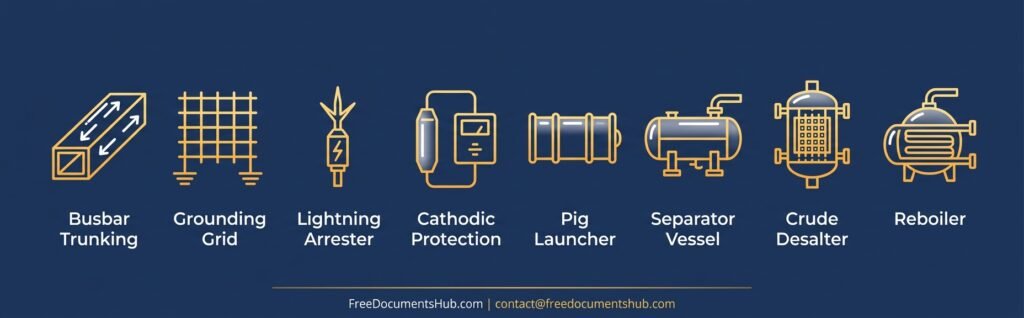
| In this package: Ready-to-use Datasheets, Method Statements, Risk Assessments, ITPs, Checklists, live Excel calculators, and completion trackers for eight commonly requested EPC systems — Busbar Trunking, Grounding Grid & Earth Pit, Lightning Arrester, Cathodic Protection, Pig Launcher/Receiver Station, Two/Three-Phase Separator Vessel, Crude Desalter Unit, and Kettle/Fixed-Tube Reboiler. Editable Word + Excel, ready for QA/QC submittal on oil & gas, EPC, and Saudi Aramco projects. |
From grounding grids to process vessels, EPC submittals all trace back to the same expectation: a consistent Datasheet → Method Statement → Risk Assessment → ITP → Checklist trail, backed by a sizing calculator that shows the numbers were actually verified — not just filled in. Electrical protection systems follow IEEE 80, IEC 62305, NFPA 780, and NACE SP0169; process vessels follow ASME Section VIII alongside API and TEMA standards.
This package covers eight of the most commonly requested systems across those two disciplines, each delivered as an 8-file bundle: Datasheet, Method Statement, Risk Assessment, ITP, Pre-Commissioning Checklist, Sizing Calculator (Excel), Completion Tracker (Excel), and cover image — so your submittals stay consistent across disciplines.
1. Busbar Trunking System
Busbar trunking carries heavy current runs between switchgear, panels, and distribution points. Commissioning documentation needs to verify every joint was torqued, insulation-tested, and continuity-checked before energizing.
Datasheet — current rating, enclosure/IP rating, busbar material, and standards references.
Method Statement — installation sequence covering support spacing, joint torque, and tap-off unit fitting.
Risk Assessment — electrical and fire hazards specific to live and energized trunking installation.
ITP — hold points for joint torque verification, insulation resistance testing, and continuity testing.
Checklist — field commissioning checklist for joints, supports, and IP rating verification.
Excel Sizing Calculator — current rating and voltage drop sizing tool.
Excel Completion Tracker — tracks completion status against design targets across each busbar run.
2. Grounding Grid & Earth Pit
Grounding grids protect personnel and equipment from step and touch potential during fault conditions. Documentation follows IEEE 80 and IEC 62305, with resistance testing as the key acceptance criterion.
Datasheet — conductor sizing, electrode spacing, soil resistivity basis, and standards references (IEEE 80, IEC 62305).
Method Statement — excavation, conductor laying, exothermic welding, and backfill sequence.
Risk Assessment — excavation, welding, and step/touch potential hazards during installation.
ITP — hold points for conductor burial depth, weld inspection, and resistance testing.
Checklist — field commissioning checklist for earth resistance measurement and connection verification.
Excel Sizing Calculator — grid conductor and resistance sizing tool per IEEE 80.
Excel Completion Tracker — tracks test point resistance results against design targets.
3. Lightning Arrester System
Lightning protection uses the rolling sphere method (IEC 62305, NFPA 780) to define air terminal placement and down conductor routing, protecting structures from direct strikes.
Datasheet — air terminal specification, down conductor sizing, and standards references (IEC 62305, NFPA 780).
Method Statement — air terminal placement using the rolling sphere method, down conductor routing, and bonding sequence.
Risk Assessment — working-at-height and lightning exposure hazards during installation.
ITP — hold points for rolling sphere zone verification and down conductor continuity testing.
Checklist — field commissioning checklist for terminal placement, bonding, and earth connection.
Excel Sizing Calculator — rolling sphere radius and down conductor sizing tool.
Excel Completion Tracker — tracks protection zone coverage against design targets.
4. Cathodic Protection System
Cathodic protection (ICCP or galvanic) prevents corrosion on buried and submerged metal per NACE SP0169 and ISO 15589-1. Commissioning hinges on pipe-to-soil potential surveys meeting protection criteria.
Datasheet — anode type, current output, potential criteria, and standards references (NACE SP0169, ISO 15589-1).
Method Statement — anode installation, rectifier setup, and potential survey sequence.
Risk Assessment — excavation, electrical, and confined space hazards during CP installation.
ITP — hold points for anode bed installation and pipe-to-soil potential survey.
Checklist — field commissioning checklist for rectifier settings and test station verification.
Excel Sizing Calculator — ICCP/galvanic anode sizing tool.
Excel Completion Tracker — tracks potential survey readings against protection criteria.
5. Pig Launcher/Receiver Station
Pig launcher/receiver stations enable pipeline cleaning and inspection runs. Documentation covers pressure boundary design per ASME B31.3/B31.4/B31.8 and ASME VIII Div. 1, plus the kicker line and barrel sizing that make a launch/receive cycle work.
Datasheet — barrel dimensions, kicker line sizing, design pressure/temperature, and standards references (ASME B31.3/B31.4/B31.8, ASME VIII Div. 1).
Method Statement — fabrication, installation, and hydrotest sequence for the launcher/receiver barrel and closure.
Risk Assessment — pressure, pigging operation, and closure-door hazards specific to launch/receive stations.
ITP — hold points for closure door testing, hydrotest, and kicker line verification.
Checklist — field commissioning checklist for closure operation, venting, and drain verification.
Excel Sizing Calculator — kicker line and barrel length sizing tool.
Excel Completion Tracker — tracks hydrotest and commissioning status against design targets.
6. Two/Three-Phase Separator Vessel
Separator vessels split incoming well fluid into gas, oil, and (for three-phase) water streams. Sizing follows ASME Section VIII for the pressure boundary and API 12J/520/521 for retention time and gas capacity.
Datasheet — vessel dimensions, retention time, gas capacity basis, and standards references (ASME VIII, API 12J/520/521).
Method Statement — vessel installation, internals fitting, and hydrotest sequence.
Risk Assessment — pressure, hydrocarbon, and lifting hazards during separator installation and testing.
ITP — hold points for internals inspection, hydrotest, and relief device verification.
Checklist — field commissioning checklist for level control, relief devices, and instrumentation.
Excel Sizing Calculator — liquid retention time and gas capacity (Souders-Brown) sizing tool.
Excel Completion Tracker — tracks commissioning test results against design targets.
7. Crude Desalter Unit
Crude desalters remove salt and water from crude ahead of downstream processing using an electrostatic field. Documentation spans the pressure vessel (ASME VIII) and the electrical/hazardous-area design of the transformer system (IEC 60079).
Datasheet — vessel dimensions, wash water injection basis, transformer power rating, and standards references (ASME VIII, IEC 60079).
Method Statement — vessel installation, electrode grid fitting, and transformer commissioning sequence.
Risk Assessment — electrical, hazardous-area, and hydrocarbon hazards specific to desalter commissioning.
ITP — hold points for electrode grid inspection, hydrotest, and transformer energization.
Checklist — field commissioning checklist for wash water injection, grid alignment, and transformer settings.
Excel Sizing Calculator — wash water injection rate and HV transformer power sizing tool.
Excel Completion Tracker — tracks commissioning milestones against design targets.
8. Kettle/Fixed-Tube Reboiler
Reboilers provide the heat duty that drives distillation columns. Sizing follows ASME Section VIII for the pressure boundary and TEMA for the heat exchanger geometry and thermal design.
Datasheet — heat duty, heat transfer area, tube bundle configuration, and standards references (ASME VIII, TEMA).
Method Statement — installation, tube bundle fitting, and hydrotest sequence.
Risk Assessment — pressure, high-temperature, and lifting hazards during reboiler installation.
ITP — hold points for tube bundle inspection, hydrotest, and steam trial.
Checklist — field commissioning checklist for steam supply, condensate return, and instrumentation.
Excel Sizing Calculator — heat duty/area and steam consumption sizing tool.
Excel Completion Tracker — tracks commissioning test results against design targets.
We Prepare These For You
All packages above are ready-made on FreeDocumentsHub.com — built to the same standards EPC contractors already use, so you’re not starting from a blank page or waiting on a vendor to send something usable.
FreeDocumentsHub.com offers full documentation service remotely. If you need a correction, a project-specific version, or a custom document built to your P&ID, we can do that — your first correction or trial document is free. Email contact@freedocumentshub.com, available 24/7.
ALL PRODUCTS IN THIS PACKAGE
| Equipment | Document | Price | Gumroad | Payhip |
| Busbar Trunking System | Single Document | $7 | View | — |
| Busbar Trunking System | Complete Package (8 Files) | $25 | View | View |
| Grounding Grid & Earth Pit | Single Document | $7 | View | — |
| Grounding Grid & Earth Pit | Complete Package (8 Files) | $25 | View | View |
| Lightning Arrester System | Complete Package (8 Files) | $25 | View | View |
| Cathodic Protection System | Complete Package (8 Files) | $25 | View | View |
| Pig Launcher/Receiver Station | Complete Package (8 Files) | $25 | View | View |
| Two/Three-Phase Separator Vessel | Complete Package (8 Files) | $25 | View | View |
| Crude Desalter Unit | Complete Package (8 Files) | $25 | View | View |
| Kettle/Fixed-Tube Reboiler | Complete Package (8 Files) | $25 | View | View |
Need a Custom Document Package for Your Project?
If your project needs a document set built to your specific P&ID, tag numbering, or project standard rather than a generic template, we can prepare it for you. Email contact@freedocumentshub.com — first correction or trial document is free, and we’re available 24/7.
Digital product — instant download (Word/Excel). No refunds on digital goods once downloaded.