
By Mohammad Iftakhar Ahmad Founder — FreeDocumentsHub.com Instrumentation and Control Engineer | 19+ Years Industrial Experience
Introduction
In any industrial facility — whether it is a chemical plant, a power generation station, an oil and gas processing facility, a water treatment plant, or a manufacturing operation — two technical disciplines form the backbone of process control and automation.
The first is loop wiring. The second is SLC design.
Together they define how field instruments communicate with control systems, how signals travel reliably from the process to the controller, and how the controller interprets those signals and sends commands back to the field. Every control loop in every industrial facility depends on both of these disciplines working correctly.
Yet despite their fundamental importance, loop wiring and SLC design are topics that many engineers learn partially — through on-the-job experience — without ever building a complete and systematic understanding of the principles involved.
This guide is designed to change that.
Whether you are an instrumentation engineer in your first years of practice, a control systems engineer looking to strengthen your fundamentals, or a site engineer who needs to understand loop wiring and SLC design to commission, troubleshoot, or maintain a control system — this guide will give you the complete technical foundation you need.
Part One — Loop Wiring
What Is a Control Loop
Before understanding loop wiring, you must understand what a control loop is.
A control loop is a closed system that monitors a process variable — such as temperature, pressure, flow, or level — compares it to a desired setpoint, and takes corrective action to bring the process variable to the setpoint and keep it there.
Every control loop has four fundamental components.
The first is the sensor or transmitter — the field instrument that measures the process variable and converts it into an electrical signal.
The second is the signal transmission path — the wiring, cables, conduits, and terminal connections that carry the electrical signal from the field instrument to the controller.
The third is the controller — the device that receives the signal, compares it to the setpoint, and determines what corrective action is needed.
The fourth is the final control element — typically a control valve, a variable speed drive, or a motor — that receives the output signal from the controller and acts on the process to bring it toward the setpoint.
Loop wiring is concerned with the second of these components — the signal transmission path. But understanding loop wiring properly requires understanding all four components and how they interact.
Types of Signals in a Control Loop
Industrial control loops use several types of electrical signals to transmit information between field instruments and controllers. Understanding these signal types is fundamental to loop wiring design.
The 4 to 20 mA current signal is by far the most common signal type in industrial instrumentation. It uses a current loop — typically powered by a 24 VDC supply — where 4 mA represents the zero or minimum value of the measured variable and 20 mA represents the full-scale or maximum value. The current signal is highly resistant to noise and voltage drops over long cable runs, making it ideal for industrial environments. A current of 4 mA — rather than 0 mA — is used deliberately so that a broken wire or instrument failure can be distinguished from a zero-process-value reading.
The 0 to 10 VDC voltage signal is used in some applications, particularly for short cable runs within panels or equipment enclosures. Voltage signals are more susceptible to noise and voltage drop over distance than current signals and are generally not recommended for long field wiring runs.
The HART protocol — Highway Addressable Remote Transducer — is a digital communication protocol superimposed on the 4 to 20 mA current signal. It allows two-way communication between a field instrument and a control system or handheld communicator. The 4 to 20 mA signal carries the process variable value as before, while the HART signal carries additional information such as instrument diagnostics, device configuration, and secondary process variables. HART is widely used in modern industrial facilities for intelligent field devices.
Digital fieldbus protocols — including Foundation Fieldbus, Profibus PA, and HART IP — replace the traditional 4 to 20 mA signal entirely with a fully digital communication bus. Multiple instruments can be connected on a single cable segment, and two-way digital communication allows far more information to be transmitted than a traditional analogue signal allows. Fieldbus systems are more complex to design and commission but offer significant advantages in terms of diagnostic capability and information density.
Discrete or binary signals — sometimes called digital input and digital output signals — carry on/off or open/closed information rather than continuously varying values. A discrete input might come from a limit switch, a push button, or a pressure switch. A discrete output might control a solenoid valve, a motor starter, or a pilot light. Discrete signals are typically 24 VDC in modern industrial systems, though 110 VAC and 230 VAC discrete signals are still found in older installations.
Thermocouple and RTD signals are low-level signals generated directly by temperature sensors. Thermocouples generate a small millivolt signal — typically in the range of a few millivolts to tens of millivolts — that varies with temperature. RTDs — Resistance Temperature Detectors — change their electrical resistance with temperature. Both signal types require special consideration in loop wiring because of their very low signal levels and susceptibility to noise and interference.
What Is a Loop Diagram
The loop diagram — also called a loop drawing or instrument loop diagram — is the most important document in instrumentation engineering. It is the complete technical drawing of a single control loop, showing every component, every connection, every terminal, every cable, and every signal type in that loop.
A well-drawn loop diagram tells a technician or engineer everything they need to know to install, commission, calibrate, troubleshoot, and maintain a control loop — without needing any other document.
A standard loop diagram includes the following information.
The field instrument — showing the tag number, the manufacturer, the model number, and the calibration range.
The junction box — showing the terminal numbers where the field cable is terminated.
The marshalling cabinet — showing the terminal numbers where the field cables arrive before being distributed to the controller.
The controller — showing the I/O card type, the card number, the channel number, and the signal type.
All cable numbers, cable specifications, and core numbers for every cable in the loop.
The power supply source for the loop — showing the panel designation, the fuse number, and the voltage.
Any barriers, isolators, or signal conditioners in the loop — with their terminal connections shown explicitly.
The grounding arrangement for the loop — showing where the shield is grounded, at which end, and to which ground terminal.
Reading a loop diagram is a fundamental skill for any instrumentation or control engineer. Drawing a loop diagram accurately and completely is an even more critical skill — because every error or omission in a loop diagram becomes a problem in the field during installation or commissioning.
Loop Wiring Design Principles
Good loop wiring design follows a set of established principles that ensure signal integrity, reliability, safety, and maintainability. These principles apply regardless of the industry, the technology, or the scale of the installation.
Use twisted pair cable for analogue signals. Twisted pair cable reduces electromagnetic interference by cancelling out induced noise. The two conductors of a twisted pair pick up approximately equal amounts of interference, and because they carry equal and opposite currents, the interference cancels at the receiving end. For 4 to 20 mA signals, always specify overall shielded twisted pair cable.
Use overall shielding and drain wire. The overall shield — typically a foil or braid surrounding all conductors — provides an additional barrier against electromagnetic interference. The drain wire — a bare conductor in contact with the foil shield — provides a convenient connection point for grounding the shield.
Ground the shield at one end only. This is one of the most important and most frequently violated rules in loop wiring. The shield must be grounded at one end only — typically at the control panel end, not at the field instrument end. Grounding the shield at both ends creates a ground loop — a path for circulating currents that introduce noise into the signal. Many instrumentation problems attributed to faulty instruments are actually caused by shields grounded at both ends.
Separate signal cables from power cables. Signal cables carrying low-level instrumentation signals must be physically separated from power cables carrying 110 VAC, 230 VAC, or higher voltages. Running signal cables in the same tray or conduit as power cables induces electromagnetic interference into the signal. Industry standards specify minimum separation distances between signal and power cables, which vary depending on the voltage levels involved.
Use separate cable trays for different signal types. Thermocouple cables should run in separate trays from 4 to 20 mA cables. Digital fieldbus cables should run separately from discrete input and output cables. This separation reduces cross-coupling between signal types and makes troubleshooting significantly easier.
Maintain consistent polarity throughout the loop. Current loops are polarity-sensitive. Reversing the polarity of connections at any point in the loop will result in incorrect readings or no signal at all. Always mark positive and negative conductors clearly and verify polarity at every termination point.
Minimise the number of terminations. Every termination is a potential point of failure — a source of contact resistance, a point where moisture can enter, and a location where wiring errors can be made. Good loop wiring design minimises the number of junction boxes, terminal strips, and intermediate connections between the field instrument and the controller.
Use the correct cable specification. Each signal type requires a specific cable specification. Thermocouple extension cables must use conductors made from the same thermocouple alloys as the thermocouple itself — using standard copper conductors for thermocouple wiring introduces additional thermoelectric junctions and measurement errors. RTD cables require low-resistance conductors and should use three-wire or four-wire configurations to compensate for lead resistance. HART and fieldbus cables have specific impedance and capacitance requirements that must be met to ensure reliable communication.
Two-Wire, Three-Wire, and Four-Wire Transmitter Configurations
One of the most important concepts in loop wiring is the distinction between two-wire, three-wire, and four-wire transmitter configurations. Understanding this distinction is essential for drawing correct loop diagrams and designing correct wiring.
A two-wire transmitter is the most common configuration in industrial instrumentation. In a two-wire transmitter, the same two conductors that carry the 4 to 20 mA signal also provide the power supply to the transmitter. The transmitter draws its operating power from the loop current. Two-wire transmitters are simple to wire, require only two conductors, and are inherently intrinsically safe-friendly because the loop current is limited.
A four-wire transmitter has a separate power supply from its output signal. Two conductors provide the power supply — typically 24 VDC or 110/230 VAC — and two separate conductors carry the 4 to 20 mA output signal. Four-wire transmitters can provide higher power levels to drive more complex measurements and are often used for analysers and complex measurement systems.
A three-wire transmitter is less common and is typically found in voltage-output devices. Two conductors provide the power supply and one conductor carries the signal, with the negative power supply conductor shared as the signal return.
The wiring configuration of a transmitter must be clearly identified before drawing the loop diagram and before purchasing cable. A common and costly error is ordering two-conductor cable for a four-wire transmitter — requiring field rework during installation.
Intrinsic Safety and Loop Wiring
For instruments installed in hazardous areas — classified as Zone 0, Zone 1, or Zone 2 for gases, or Zone 20, Zone 21, or Zone 22 for dust — intrinsic safety is one of the most important explosion protection methods used in loop wiring.
An intrinsically safe loop is one where the electrical energy in the loop — under both normal operation and fault conditions — is insufficient to ignite a flammable atmosphere. This is achieved by limiting the voltage, current, and stored energy in the loop using Zener barriers or galvanic isolators installed in the safe area.
Intrinsic safety imposes specific requirements on loop wiring. The cable must have defined maximum capacitance and inductance values that do not exceed the entity parameters of the barrier and instrument combination. Safe area and hazardous area wiring must be physically separated — they cannot share the same cable tray or conduit. Blue-sheathed cable is commonly used for intrinsically safe circuits to distinguish them visually from non-IS circuits.
Every intrinsically safe loop must have a documented safety certificate or entity calculation confirming that the combination of barrier, cable, and instrument is certified as intrinsically safe. This documentation is a legal requirement in most jurisdictions and a fundamental audit requirement for facilities operating under ATEX, IECEx, or national hazardous area regulations.
Common Loop Wiring Problems and How to Avoid Them
Understanding common loop wiring problems helps you design better systems and troubleshoot existing installations more effectively.
Ground loops are the single most common cause of noisy or erratic 4 to 20 mA signals. They are caused by shielding grounded at more than one point, creating a path for circulating currents. The solution is strict discipline in grounding only at one end — typically the panel end — and verifying shield continuity and isolation at the instrument end during commissioning.
Incorrect cable specification causes problems that are difficult to diagnose because the symptoms — noise, signal drift, communication errors — can look like instrument faults. Always verify that cable capacitance, inductance, resistance, and shielding specification meet the requirements of the signal type and the instrument documentation.
Voltage drop on long cable runs can cause a two-wire transmitter to receive insufficient supply voltage, particularly at low loop currents near 4 mA. Calculate the voltage available at the transmitter for the maximum cable length and the minimum loop current, and verify that it exceeds the transmitter’s minimum supply voltage requirement.
Moisture ingress at junction boxes and instrument connections causes signal degradation and corrosion over time. Use weatherproof junction boxes rated for the installation environment, ensure all cable entry glands are correctly installed and sealed, and verify that all unused entries are correctly blanked.
Incorrect polarity connections are common during installation, particularly when multiple cables arrive at a junction box simultaneously. Colour-coded cores, clear labelling, and systematic polarity verification at every termination point during installation prevents this problem.
Part Two — SLC Design
What Is an SLC
SLC stands for Small Logic Controller — a term most commonly associated with the Allen-Bradley SLC 500 series of programmable logic controllers manufactured by Rockwell Automation. However the principles of SLC design apply broadly to small and medium-scale PLC-based control systems from any manufacturer.
An SLC is a programmable controller used to implement discrete logic control, analogue control, sequential control, and simple closed-loop control in industrial applications. The SLC 500 series — introduced in the 1980s and still widely used in installed base — uses a modular rack-based architecture, a proprietary programming language called ladder logic, and a range of input and output modules that interface with field devices.
Understanding SLC design means understanding how to select the correct hardware — rack, processor, and I/O modules — how to organise and document the I/O configuration, how to write ladder logic programs that implement the required control functions, and how to commission, test, and document a complete SLC-based control system.
SLC Hardware Architecture
The SLC 500 system is built around a modular rack architecture. The rack provides the backplane — the internal communication bus — that connects the processor to the I/O modules. Racks are available in 4-slot, 7-slot, 10-slot, and 13-slot configurations depending on the number of I/O modules required.
The processor is the brain of the SLC system. It executes the ladder logic program, communicates with I/O modules through the backplane, and manages communications with programming software, HMI systems, and other controllers. SLC 500 processors range from the basic SLC 5/01 and SLC 5/02 to the more capable SLC 5/03, SLC 5/04, and SLC 5/05, with differences in memory size, communication ports, and instruction set capability.
I/O modules are the interface between the SLC processor and the field devices. They convert field signals — voltages, currents, contact states — into digital data that the processor can read and process. They also convert processor output data into signals that can drive field actuators — valves, motors, indicator lights, and solenoids.
Discrete input modules accept binary signals from field devices such as push buttons, limit switches, pressure switches, proximity sensors, and relay contacts. Common module types include 24 VDC input modules, 120 VAC input modules, and 230 VAC input modules.
Discrete output modules send binary signals to field actuators. Common types include 24 VDC transistor output modules, relay output modules — which provide dry contact outputs — and 120 VAC triac output modules.
Analogue input modules accept continuous signal values from field transmitters — most commonly 4 to 20 mA or 0 to 10 VDC signals — and convert them to digital values that the processor can use in calculations and control algorithms.
Analogue output modules convert digital values from the processor into continuous signals — typically 4 to 20 mA — that can drive control valves, variable speed drives, and other analogue actuators.
Specialty modules include thermocouple and RTD input modules, high-speed counter modules, ASCII communication modules, and network communication modules.
SLC I/O Addressing
Every input and output in an SLC system has a unique address that the ladder logic program uses to reference it. Understanding I/O addressing is fundamental to SLC programming and documentation.
In the SLC 500 system, I/O addresses follow a specific format — File Type colon Slot Number slash Bit Number.
For discrete inputs, the address format is I colon slot slash bit. The letter I identifies the file type as input. The slot number identifies which rack slot the input module occupies. The bit number identifies which input terminal on that module is being referenced. For example I colon 1 slash 3 refers to input terminal 3 on the module in slot 1.
For discrete outputs, the address format is O colon slot slash bit, following the same structure as discrete inputs but using the letter O for output.
For analogue inputs and outputs, the address format uses N for integer files or F for floating-point files, with the file number, word number, and bit number specified according to the module configuration.
Word-level addresses are used for analogue signals. For a standard SLC 500 analogue input module configured for 4 to 20 mA input, the raw analogue value is stored as an integer in the input file. The processor scales this integer value — typically ranging from 0 to 32767 for a full 4 to 20 mA range — into engineering units using scaling instructions in the ladder logic program.
SLC Ladder Logic Design Principles
Ladder logic is the graphical programming language used for SLC and PLC programming. It was designed to resemble the relay logic circuits that it replaced, making it accessible to electricians and control engineers who were familiar with relay schematic diagrams.
A ladder logic program consists of rungs — horizontal lines in the program — that connect power flow from left to right through contacts and output coils. Each rung represents a logical statement — if these conditions are true, then perform this action.
Good ladder logic design follows principles that make programs reliable, readable, maintainable, and safe.
Structure the program logically. Organise your ladder program into clearly separated sections — input processing, safety and permissive logic, control logic, output processing, and fault handling. A well-structured program allows any engineer to navigate it quickly and understand the control strategy without extensive documentation.
Use descriptive tags and comments. Every input, output, and internal bit in the program should have a tag name that describes what it represents — not just an address. A tag named PUMP1 RUN STATUS is immediately understandable. A tag that is just O colon 2 slash 7 tells the next engineer nothing without referring to the I/O list. Comment every rung to explain what it does and why.
Implement safety logic correctly. Safety-critical functions — emergency stops, high-high trips, safety interlocks — must be implemented using normally closed contacts in series with the control output. This means that if the safety input wiring is broken or the safety device fails de-energised, the safety function activates. Never implement safety logic using normally open contacts that must close to trip the system — a broken wire in this configuration will leave the safety function inactive.
Avoid latching outputs without corresponding unlatch conditions. Any output bit that is latched — set to 1 and held — must have a clearly defined and unconditional unlatch condition. Runaway latched outputs that cannot be cleared by normal operation are a common cause of control system problems that are difficult to diagnose.
Handle analogue scaling carefully. When scaling analogue input values from raw integer counts to engineering units, ensure that the scaling is correct for the full range of the signal — including the underrange condition at 4 mA or 0 counts and the overrange condition above 20 mA. Implement out-of-range detection and alarm logic to catch broken transmitter wiring and instrument faults.
Implement first-out fault annunciation. In systems with multiple interlock conditions, it is essential to capture which interlock tripped first — before subsequent interlocks activate. First-out annunciation logic uses a one-shot — a single-scan pulse — to capture and latch the first interlock that changes state during a trip sequence. Without first-out logic, a single root-cause trip can activate multiple interlocks simultaneously, making the root cause impossible to identify from the alarm system.
Use internal control bits to separate logic from physical outputs. Write your control logic to set and reset internal control bits — not directly to physical output coils. The physical output coil should be a single rung at the end of the program that is driven by the internal control bit. This structure makes the program easier to test, simulate, and modify without affecting physical outputs.
SLC I/O List and Documentation
A complete SLC design includes a comprehensive I/O list — sometimes called an I/O schedule or I/O assignment table — that documents every input and output in the system.
A well-structured I/O list includes the following information for every I/O point.
The I/O address — the full SLC address of the point in the format described above.
The tag name — the descriptive name used in the ladder logic program.
The signal type — whether the point is a discrete input, discrete output, analogue input, analogue output, and the specific signal type within that category.
The field device description — a plain-language description of the field instrument or actuator connected to this I/O point.
The instrument tag number — the P and ID tag number of the field instrument.
The engineering unit and range — for analogue points, the engineering unit of measurement and the zero and full-scale values corresponding to 4 mA and 20 mA.
The alarm setpoints — for analogue inputs, the low alarm, low-low alarm, high alarm, and high-high alarm setpoints.
The safety function — whether the point is used in a safety interlock and what the safe state is.
The I/O list is the primary reference document during SLC panel wiring, during commissioning, and during ongoing operations and maintenance. It must be kept up to date whenever the system is modified.
SLC Panel Design and Wiring
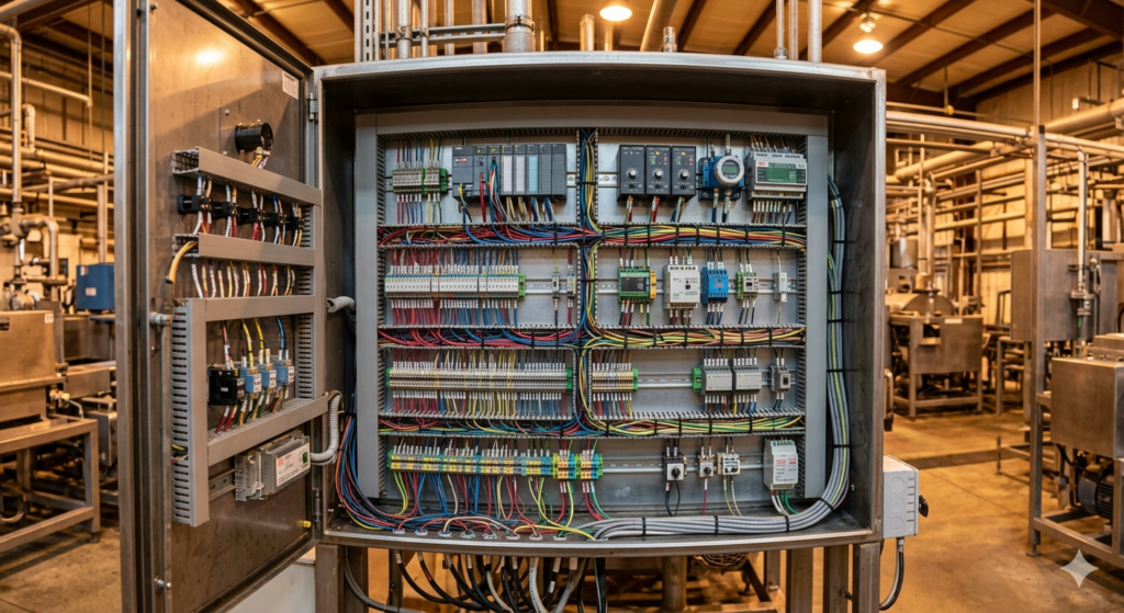
The SLC control panel is the physical enclosure that houses the SLC rack, the power supply, the terminal blocks, the cable management system, and the associated auxiliary components.
Good SLC panel design follows these principles.
Size the enclosure correctly. The panel must provide sufficient space for the SLC rack and all associated components, with adequate clearance for heat dissipation, cable routing, and maintenance access. Overcrowded panels are difficult to maintain and are prone to overheating.
Use DIN rail-mounted terminal blocks for all field connections. Terminal blocks provide a clear, accessible, and documented interface between the field wiring and the SLC I/O modules. Every field cable should terminate at a terminal block — never connect field cables directly to I/O module terminals without terminal blocks.
Separate analogue and discrete wiring within the panel. Even inside the panel enclosure, analogue signal wiring should be routed separately from discrete wiring and power wiring to minimise interference.
Provide individual fusing for each output circuit. Each discrete output — particularly outputs driving inductive loads such as solenoid valves and motor contactors — should be individually fused. This limits fault current and protects the I/O module from damage in the event of a field wiring short circuit.
Use surge protection on analogue inputs. Field analogue signals can carry transient voltages caused by lightning strikes, switching transients, or ground faults in the field. Surge protection devices installed on analogue input terminals protect the I/O module from these transients.
Label every terminal, every wire, and every component. A well-labelled panel allows any engineer or technician — including someone seeing it for the first time — to understand the wiring, locate components, and trace circuits without referring to drawings. Every wire should be labelled at both ends.
SLC Commissioning and Testing
A well-designed SLC system must be rigorously commissioned and tested before being placed in service.
The first stage of commissioning is a factory acceptance test — FAT — conducted before the panel leaves the workshop. The FAT verifies that all hardware is correctly installed and wired, that the ladder logic program compiles without errors, that all I/O points respond correctly to simulated inputs and drive outputs correctly, and that all safety interlocks function as designed.
The second stage is site acceptance testing — SAT — conducted after the panel is installed on site and connected to field instruments and actuators. The SAT verifies that all field wiring is correctly connected, that every instrument transmits the correct signal to the correct I/O address, that every output drives the correct field device, and that the complete control loop — from field instrument through the controller to the final control element — functions correctly under actual process conditions.
A complete commissioning record must be produced for every I/O point — documenting the as-found and as-left conditions, the test method, the result, and the signature of the commissioning engineer. This record is an essential part of the system documentation and is required by most quality management systems and regulatory bodies.
The Relationship Between Loop Wiring and SLC Design
Loop wiring and SLC design are inseparable disciplines. A perfectly designed SLC program is useless if the loop wiring delivers a noisy, incorrect, or unreliable signal to the I/O module. A perfectly wired loop is useless if the SLC program interprets the signal incorrectly, applies the wrong scaling, or implements incorrect control logic.
The interface between the two disciplines is the I/O module — the point where the physical signal from the field wiring becomes digital data in the SLC processor. Understanding both disciplines — and understanding how they interact at this interface — is what distinguishes a complete instrumentation and control engineer from a specialist in only one area.
When troubleshooting a control problem, the engineer who understands both loop wiring and SLC design can quickly and systematically isolate whether the problem is in the field wiring, the I/O module, the scaling logic, the control algorithm, or the output circuit. The engineer who understands only one discipline will take far longer to find the root cause — and may misdiagnose the problem entirely.
Career Implications for Engineers
Proficiency in loop wiring and SLC design opens significant career opportunities across multiple industries worldwide.
The demand for instrumentation and control engineers with practical loop wiring and PLC design skills remains consistently high in oil and gas, petrochemicals, power generation, water treatment, food and beverage, pharmaceuticals, and manufacturing.
The ability to read and draw loop diagrams is a fundamental requirement for instrumentation engineering roles at all levels. The ability to design, program, and commission SLC and PLC systems adds significant value to any instrumentation engineer’s profile.
For engineers seeking positions with major operators like Saudi Aramco, ADNOC, SABIC, Shell, ExxonMobil, or major EPC contractors, competency in both loop wiring and SLC/PLC design is not just advantageous — it is frequently listed as a mandatory requirement.
Building this competency requires both theoretical understanding — which this guide has provided — and practical experience. Seek out every opportunity to draw loop diagrams, to wire instrument loops, to read SLC programs, and to commission control systems. The combination of theoretical knowledge and practical skill is what the industry rewards most highly.
Conclusion
Loop wiring and SLC design are two of the most practically important technical disciplines in instrumentation and control engineering.
Loop wiring provides the reliable signal transmission that every control system depends on. Without well-designed, correctly installed, and properly grounded loop wiring, even the most sophisticated controller cannot function correctly.
SLC design provides the intelligence that translates those signals into control actions. Without well-structured, correctly programmed, and thoroughly tested ladder logic, even the most perfectly wired system cannot achieve its control objectives.
Together they form the foundation of industrial automation — the disciplines that keep process plants running safely, efficiently, and reliably.
Whether you are designing a new system, commissioning an existing one, or troubleshooting a persistent problem in the field — a thorough understanding of loop wiring principles and SLC design practices will give you the knowledge and confidence to do the job correctly.
The best instrumentation and control engineers are not just theorists. They are practitioners who understand exactly how signals travel from the process to the controller and back again — and who can design, build, and maintain the systems that make this happen reliably every day.
If you found this guide useful, explore our complete library of instrumentation and control engineering documentation, templates, and training resources at www.freedocumentshub.com. We provide professional documentation support for engineers and companies worldwide.
What topic in instrumentation or control engineering would you like us to cover next? Share in the comments below.
Mohammad Iftakhar Ahmad Founder — FreeDocumentsHub.com contact@freedocumentshub.com www.freedocumentshub.com