
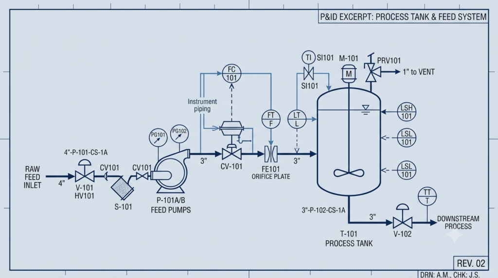
A Piping and Instrumentation Diagram, almost always shortened to P&ID, is the single drawing that tells you what a process unit actually does once it is built. It shows every line, every valve, every instrument, and every piece of equipment, along with how they are all wired together in the real, physical sense. If you can read a P&ID confidently, you can walk into almost any fabrication shop, refinery, or gas plant and understand the process in front of you within the hour — which is exactly what this crash course is built to do.
| Need Help With Your Industrial Documents? We provide remote documentation services for all industrial document types — WPS, PQR, ITP, NCR, ASME code documentation, P&ID reviews, and more — for fabrication and engineering companies worldwide. Available 24×7. Contact us for a free trial or to place an order. |
1. What a P&ID Actually Is (and Is Not)
A P&ID is not a 3D model, and it is not drawn to scale. It is a schematic — a logic diagram of the process. Distances, elevations, and physical layout are deliberately ignored so the drawing can focus on one job: showing the correct sequence of equipment, piping, valves, and instrumentation needed to run the process safely.
It sits inside a family of process drawings, and mixing these up is one of the most common early mistakes:
| Drawing | What It Shows |
| PFD (Process Flow Diagram) | The big picture: major equipment, mass balance, and flow direction. No valves, no instrument detail. |
| P&ID | Every line, valve, instrument, and interlock — the level of detail used for construction, operation, and safety review. |
| Isometric drawing | The physical pipe routing in 3D space, with dimensions, used by fabricators and fitters. |
| Line list | A spreadsheet companion to the P&ID — line number, size, spec, material, insulation, and service for every line shown. |
2. The Four Elements You Are Actually Reading
Every P&ID, regardless of licensor or plant, is built from four repeating families of symbols. Once you can recognize these four at a glance, the rest of the drawing becomes vocabulary, not a mystery.
2.1 Equipment
Vessels, pumps, compressors, heat exchangers, and tanks are drawn as simplified outlines — a pump is a circle with a triangle, a vessel is a tall rectangle or oval, a heat exchanger is a set of parallel lines inside a shell shape. Equipment carries a tag such as V-101 (vessel), P-201A/B (pump, with spare), or E-301 (exchanger), and that tag is the key you use to cross-reference the equipment list and datasheets.
2.2 Piping Lines
Lines are the arteries of the drawing. The line type tells you what is flowing and how it is drawn matters as much as where it goes:
| Line Style | Meaning |
| Solid heavy line | Main process piping — the primary flow path. |
| Solid thin line | Utility or secondary piping (steam, air, nitrogen). |
| Dashed line | Instrument signal line (pneumatic or electronic). |
| Dash-dot line | Electrical signal or data line. |
| Line with hash marks | Insulated or heat-traced line. |
Each line also carries a line number in a fixed sequence — typically size, then service code, then a sequential number, then piping spec, for example 6″-P-1042-A1B. Learning to decode this one string tells you the pipe size, what it carries, and its material spec without opening the line list.
2.3 Valves and In-Line Components
Valve symbols are simple geometric shapes, and the shape — not a label — tells you the valve type. A gate valve is a bowtie. A globe valve is a bowtie with a curved line through it. A check valve is a bowtie with an arrow or flap. A control valve adds an actuator symbol (a small square or diamond) on top of the body symbol, immediately flagging it as automated rather than manually operated.
- Bowtie, plain — gate or ball valve (on/off service)
- Bowtie with internal curve — globe valve (throttling service)
- Bowtie with arrow — check valve (one-directional flow)
- Bowtie with actuator symbol on top — control valve, automated
- Circle with X — plug valve
2.4 Instrumentation — the ISA 5.1 Bubble System
This is the part that intimidates most first-time readers, and it is also the part that unlocks everything once it clicks. Every instrument on a P&ID is drawn as a circle (a ‘bubble’), and the letters inside that bubble are not random — they follow the ISA 5.1 standard, read top-to-bottom and left-to-right.
The first letter tells you what is being measured. The following letters tell you what the instrument does with that measurement:
| Succeeding Letter | Function |
| I | Indicator — shows a local reading |
| C | Controller — actively adjusts the process |
| T | Transmitter — sends the signal elsewhere |
| A | Alarm — triggers a warning at a set point |
| S | Switch — triggers a discrete on/off action |
| V | Valve — the final control element itself |
Read them together and a tag like PIC-204 stops being a code and becomes a sentence: a Pressure Indicating Controller, instrument loop number 204. PSHH-310 becomes Pressure Switch, High-High, loop 310 — almost certainly wired into a shutdown system. Once you can sound out a bubble the way you’d sound out a word, you can read the safety intent of the whole loop without a legend in front of you.
3. The Bubble Border Tells You Where the Signal Lives
The line style around the bubble matters as much as the letters inside it — it tells you where that instrument physically sits and how its signal travels:
| Bubble Border | Location |
| Plain circle, no line | Field-mounted, locally read only |
| Circle with single horizontal line | Mounted on the main control panel, control room |
| Circle with double horizontal line | Mounted on a local or auxiliary panel |
| Circle inside a square (or hexagon) | Part of the DCS or PLC logic — software-based, not a physical box |
4. The One-Hour Reading Method
Follow this sequence on any unfamiliar P&ID and you will have a working understanding inside an hour. Do not skip ahead — the order matters because each step builds context the next step depends on.
- Read the title block and legend first (5 min). Confirm the revision, the unit, and the drawing’s own symbol legend — licensors vary slightly, and the legend overrides any general convention.
- Trace the main process line start to finish (10 min). Follow the heaviest solid line from feed to product, ignoring every branch on the first pass. This gives you the skeleton of the process.
- Identify every major equipment tag on that main line (10 min). Note vessel, pump, and exchanger tags in order — this is your equipment sequence.
- Go back and read every valve on the main line (10 min). Note which are manual, which are control valves, and which are check valves — this tells you where the process is actively controlled versus passively protected.
- Decode every instrument bubble on the main line (15 min). Sound out each tag using the ISA table above. Group them by loop number — most loops have 2–4 bubbles working together (a transmitter, a controller, a valve, and often an alarm).
- Trace utility and secondary lines last (10 min). Steam, nitrogen purge, flare, and drain lines usually make sense only after the main process is understood.
| Common Reading Mistakes That Cause Field Problems Confusing a normally-open and normally-closed valve symbol on shutdown valves — always check the fail position note, not just the body symbol. Reading a PFD-level understanding into a P&ID review and missing a bypass line or spare pump that only appears at P&ID detail. Ignoring the interlock logic tied to alarm-tagged instruments (PSHH, LSLL) — these drive emergency shutdown sequences and are frequently the source of an NCR when field routing doesn’t match the drawn logic. |
5. Why This Matters Beyond the Drawing
For a fabrication shop pursuing Aramco AVL registration or ASME certification, P&ID literacy is not academic. Inspectors, QC reviewers, and client engineers reference P&ID line numbers and instrument tags constantly during ITP walkdowns and NCR investigations. A shop that can trace a line number back to its P&ID origin in seconds — instead of paging through a stack of drawings — closes inspection points faster and avoids the kind of documentation gaps that turn into findings.
The same fluency carries directly into systems integration work: reading a client’s existing P&ID accurately is the first step before a monitoring or protection system, such as a flare gas analyzer or a rotating equipment condition monitor, can be specified and installed correctly.
| Need Help With Your Industrial Documents? We provide remote documentation services for all industrial document types — WPS, PQR, ITP, NCR, ASME code documentation, P&ID reviews, and more — for fabrication and engineering companies worldwide. Available 24×7. Contact us for a free trial or to place an order. |