
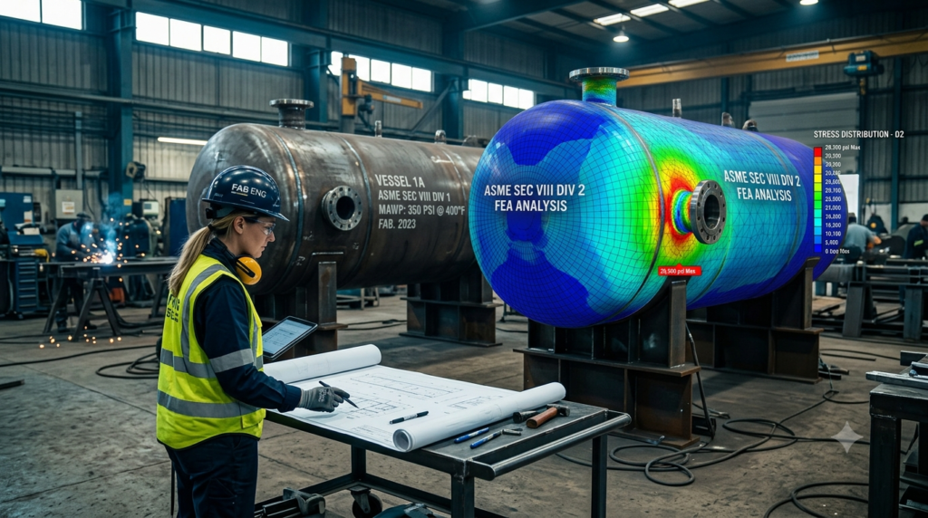
A practical breakdown of design philosophy, allowable stress, documentation load, and cost — so you choose the right Division before the vessel is ever ordered.
| Need Remote Industrial Documentation — Fast? FreeDocumentsHub.com delivers WPS, PQR, ITP, MDR, and code-compliance documentation remotely, 24×7 — wherever your project is. Start with a free trial or order directly via WhatsApp. → Free Trial Available | → Order via WhatsApp | → 24×7 Remote Support |
Why This Decision Matters Before Design Starts
Every pressure vessel project reaches a fork in the road early: build to ASME Section VIII Division 1, or step up to Division 2. Get it wrong and you either pay for engineering rigor you didn’t need, or you under-engineer a vessel that will spend its service life in cyclic, high-pressure, or high-temperature conditions it was never analyzed for. This choice shapes everything downstream — material selection, wall thickness, NDE scope, fabrication tolerances, and the entire documentation package: WPS, PQR, MTRs, ITP, and the Manufacturer’s Data Report (MDR).
This article breaks down the real engineering and commercial differences between the two Divisions, so procurement, design, and QA teams can align on the right code path before a single plate is cut.
The Core Philosophy: Design by Rule vs Design by Analysis
Division 1 is built on Design by Rule. Wall thickness, nozzle reinforcement, and head geometry are calculated using prescriptive formulas found directly in the code — no detailed stress analysis is mandated for standard configurations. This makes Division 1 fast to design, easy to check, and forgiving for shops without in-house finite element capability.
Division 2 takes the opposite approach: Design by Analysis. Rather than relying solely on simplified formulas, Division 2 permits — and in many cases requires — detailed stress analysis, often using finite element methods, to demonstrate that stresses at every critical location remain within allowable limits under all specified loading conditions, including cyclic loads. This is the single biggest philosophical difference between the two Divisions, and it cascades into every other distinction below.
Allowable Stress and Design Margin
Division 1 applies a design margin of 3.5 against the material’s ultimate tensile strength. Division 2 tightens that margin to 3.0 (reduced from 2.4 in earlier editions), which directly raises the allowable stress value for the same material and temperature.
The practical effect: for an identical design pressure and diameter, a Division 2 vessel can often be built with a thinner wall than its Division 1 equivalent. That’s real savings in plate material, welding consumables, weld volume, and weight — savings that can offset the higher engineering and inspection cost, especially on large or thick-wall vessels.
Fatigue: The Requirement That Changes Everything
Division 1 does not generally require fatigue analysis. Division 2, by contrast, mandates a fatigue evaluation under Part 5 whenever the vessel is subject to cyclic operation — pressure cycling, thermal cycling, or mechanical loading that repeats over the vessel’s service life.
This single requirement is often the deciding factor in Division selection. A reactor, a vessel with frequent startup/shutdown cycles, or equipment exposed to thermal shock is a strong candidate for Division 2 regardless of wall-thickness savings, simply because Division 1 has no built-in mechanism to catch fatigue-driven failure modes.
Material Toughness and Impact Testing
Because Division 2 vessels typically operate at higher stress utilization and are more likely to see cyclic or low-temperature service, its impact-testing requirements are more stringent and apply across a broader combination of thickness and minimum design metal temperature (MDMT). Division 1’s impact-testing exemption curves are more forgiving, which is part of why Division 1 remains the default for straightforward, non-cyclic, moderate-temperature service.
NDE Scope and Acceptance Criteria
Division 1 allows selective (spot) radiography for many joint categories, with acceptance criteria tied to the joint efficiency the fabricator wants to claim. Division 2 generally demands more extensive NDE — full radiography or equivalent volumetric examination on a wider range of joints — paired with tighter acceptance criteria, consistent with the higher allowable stresses being used.
For a documentation team, this means the NDE report package for a Division 2 vessel is materially larger: more RT film or digital records, more UT/PT/MT reports, and tighter cross-referencing between the radiography map and the final MDR.
The Documentation Burden: What Changes in Practice
- Design Report: Division 2 requires a full design report documenting the analysis method, load cases, and fatigue evaluation — Division 1 does not.
- WPS/PQR: Both Divisions require qualified welding procedures, but Division 2’s tighter acceptance criteria often mean more conservative essential variables and more PQR test coupons per procedure.
- ITP (Inspection & Test Plan): Division 2 ITPs carry more hold points, more witness/monitor points from the Authorized Inspector, and more detailed NDE sign-off stages.
- MDR (Manufacturer’s Data Report): The Division 2 MDR is thicker — it must include the design report, fatigue calculations, and a more granular NDE record set alongside the standard U-1A/U-1B forms.
Teams that treat documentation as an afterthought on Division 2 projects consistently run into schedule slippage at the data-book stage — not because the welding or fabrication was wrong, but because the paperwork wasn’t built in parallel with the fabrication sequence.
Cost and Schedule: Where the Trade-Off Actually Lands
Division 1 wins on engineering speed and upfront cost — fewer calculations, fewer required specialists, faster code-check turnaround. Division 2 wins on material efficiency and long-term suitability for demanding service, but only if the project has the engineering bandwidth (or a qualified external partner) to handle the design report, fatigue analysis, and expanded documentation without derailing the schedule.
As a rule of thumb: for storage tanks, air receivers, and general process vessels running at moderate, steady pressure, Division 1 remains the pragmatic default. For high-pressure reactors, thick-wall equipment, or anything with meaningful cyclic service, Division 2’s tighter margins and mandatory fatigue analysis are what actually keep the vessel safe over its design life — the extra documentation is the price of that safety margin, not a bureaucratic add-on.
Side-by-Side Comparison
| Aspect | Division 1 | Division 2 |
| Design Approach | Design by Rule (simplified formulas) | Design by Analysis (detailed stress analysis permitted/required) |
| Design Margin (Factor of Safety) | 3.5 on ultimate tensile strength | 3.0 (previously 2.4) — tighter margin, higher allowable stress |
| Allowable Stress | Lower — more conservative | Higher — thinner walls possible for same MAWP |
| Fatigue Analysis | Not typically required | Mandatory fatigue evaluation per Part 5 |
| Material Toughness (Impact Testing) | Required only below certain thickness/temperature thresholds | More stringent impact-testing requirements across broader ranges |
| NDE Requirements | Selective, category- and joint-dependent | More extensive — full radiography and stricter acceptance criteria typical |
| Documentation Burden | Moderate — standard MDR, WPS/PQR, NDE reports | Heavy — full design report, fatigue calculations, detailed MDR |
| Fabrication & QC Rigor | Standard shop QC program | Enhanced QC program with more inspection hold points |
| Typical Applications | Storage tanks, air receivers, general process vessels | High-pressure reactors, thick-wall vessels, cyclic-service equipment |
| Engineering Cost & Time | Lower — faster design cycle | Higher upfront cost — offset by thinner walls, less material |
Making the Call on Your Next Project
The Division decision should be made at the front end of the project — during specification, not after the vessel is already being fabricated. Ask three questions early: Is the service cyclic? Does the pressure/thickness combination make a thinner Division 2 wall commercially attractive? Does the fabricator and engineering team have the bandwidth to carry a full design report and expanded NDE/documentation package without slipping the schedule?
Answering those honestly — before the PO is cut — avoids the two most common and expensive mistakes on pressure vessel projects: over-engineering a simple storage vessel to Division 2 standards, or under-engineering a cyclic-service reactor to Division 1 and inheriting a fatigue-driven failure years into operation.
| Get Your Documentation Done Right — Remotely, Anytime Whether you’re working to ASME Section VIII Division 1 or Division 2, FreeDocumentsHub.com’s remote documentation team supports fabrication shops, engineers, and inspectors 24×7 — no site visit required. Try it free or message us on WhatsApp to get started today. → Start Your Free Trial | → Chat on WhatsApp | → 24×7 Global Coverage |