
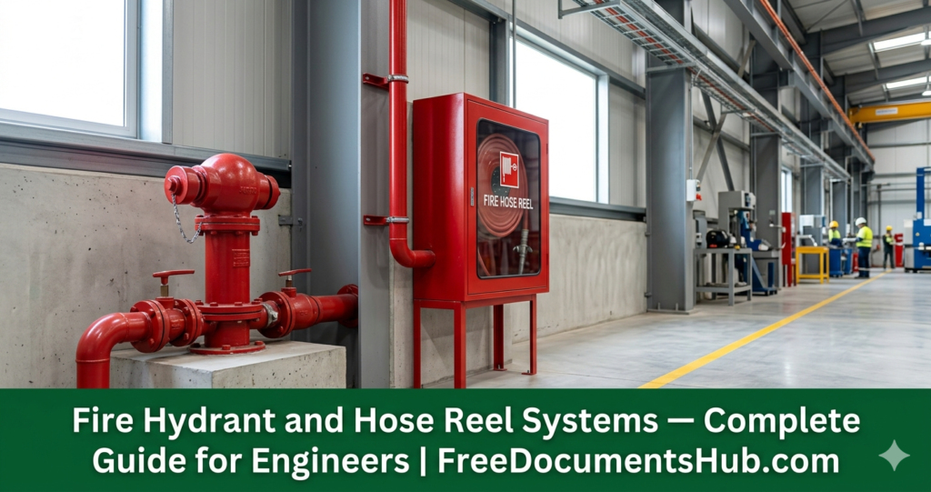
Fire hydrant and hose reel systems are the first line of active firefighting defence on any industrial, commercial, or infrastructure facility. When a fire breaks out, the speed and effectiveness of the initial response depends entirely on whether these systems were designed correctly, installed properly, tested thoroughly, and maintained consistently.
This guide covers everything a fire protection engineer, HSE officer, or QA/QC inspector needs to know — from design principles to installation requirements, testing procedures, and the standards that govern every aspect of these systems.
What Is a Fire Hydrant System?
A fire hydrant system is a network of underground or above-ground pressurised water pipework installed throughout a facility, terminating at hydrant outlets at strategic locations. It provides a high-volume water supply for firefighting by the fire brigade or trained on-site fire teams using hoses and branch pipes.
Fire hydrant systems are designed for large-scale firefighting — controlling or extinguishing fires in buildings, process areas, storage yards, and open areas where hose reel systems cannot provide sufficient water volume.
Key design parameters:
- Flow rate: Minimum 1,000 litres per minute at the hydraulically most remote hydrant — NFPA 24 / BS EN 14384
- Residual pressure: Minimum 6.9 bar (100 psi) at the outlet during flow — NFPA 13 / NFPA 24
- Coverage radius: Maximum 60 metres from hydrant to the furthest point of the protected area (with 30 metre hose length)
- Hydrant spacing: Maximum 120 metres between hydrants along access roads — SAES-B-067 for Aramco facilities
What Is a Hose Reel System?
A hose reel system provides a first-aid firefighting capability for building occupants before the fire brigade arrives. It consists of a permanently connected, semi-rigid hose wound on a reel — fed from a pressurised water supply — allowing a single person to fight a small fire without training or special equipment.
Hose reels are designed for early-stage fire intervention — they are not a substitute for sprinkler systems or fire brigade response. Their purpose is to give building occupants a fighting chance in the critical first minutes of a fire.
Key design parameters:
- Hose length: 30 metres — every point in the building must be reachable from at least one hose reel
- Flow rate: Minimum 24 litres per minute at any point with all hose reels in the same zone operating simultaneously — BS 5306-1
- Pressure: Minimum 2.0 bar at the nozzle during flow
- Coverage: Every point in the building within 6 metres of the hose nozzle when the hose is fully extended
Applicable Standards
Every fire protection engineer working in the GCC must know these standards:
| Standard | Title | Application |
|---|---|---|
| NFPA 24 | Standard for the Installation of Private Fire Service Mains and Their Appurtenances | Underground and above-ground hydrant pipework |
| NFPA 14 | Standard for the Installation of Standpipe and Hose Systems | Hose systems in buildings |
| NFPA 291 | Recommended Practice for Fire Flow Testing and Marking of Hydrants | Hydrant flow testing |
| BS EN 14384 | Above-ground fire hydrants | Hydrant product standard |
| BS 5306-1 | Fire extinguishing installations — Hose reels with semi-rigid hose | Hose reel design and installation |
| SAES-B-067 | Saudi Aramco Fire Protection Standard | All fire protection on Aramco facilities |
| NFPA 13 | Standard for the Installation of Sprinkler Systems | Integration with sprinkler systems |
| ISO 14816 | Road vehicles — Numbering systems for fire hydrants | Hydrant identification |
Fire Hydrant System Components
A complete fire hydrant system consists of the following components — every engineer must understand each one:
1. Fire Water Storage Tank The dedicated fire water reserve — sized to supply the required flow rate for the required duration. NFPA 22 governs tank design. Minimum storage: sufficient for 2 hours of firefighting at design flow rate. The tank must be dedicated to fire protection — no other use permitted.
2. Fire Pump Set Consists of three pumps working together:
- Main pump — electric motor driven, provides the design flow and pressure
- Standby pump — diesel engine driven, starts automatically on main pump failure or on mains power failure. Diesel pump is the safety net — it must be able to run independently of any electrical supply
- Jockey pump (pressure maintenance pump) — small pump that runs continuously to maintain system pressure and detect small leaks. When jockey pump cannot maintain pressure — main pump starts automatically
3. Underground Pipework Ductile iron or HDPE pipe buried at minimum 600mm cover depth. Pipe network designed as a ring main where possible — so any section can be isolated for maintenance without losing coverage to the entire site. All underground joints must be restrained — thrust blocks at all bends, tees, and changes in direction.
4. Above-Ground Pipework and Valves Above-ground sections in galvanised steel or ductile iron. Isolation valves at each hydrant branch — so individual hydrants can be isolated without shutting down the entire system. All valves must be supervised — open/closed position monitored and alarmed at the fire alarm panel.
5. Landing Valves (Pillar Hydrants) The outlet connection point for firefighting hoses. Two types:
- Pillar hydrant — free-standing above ground, used in open areas and along access roads
- Wall hydrant / wet riser outlet — mounted on building walls at each floor level for multi-storey buildings
Landing valve outlet size: 65mm (2.5 inch) — standard connection for fire brigade hose
6. Hose Cabinet Weatherproof cabinet adjacent to each hydrant containing: 30 metre delivery hose, branch pipe and nozzle, hydrant key (bar). Cabinet must be red, clearly labelled, and accessible 24 hours.
7. Pressure Gauges and Test Points Pressure gauges at pump sets, at the system inlet, and at the hydraulically most remote hydrant. Test points for flow testing at each hydrant.
Hose Reel System Components
1. Hose Reel Unit Swing-arm or recessed reel mounted on wall. Semi-rigid polyethylene hose — 19mm internal diameter — wound on reel. Permanently connected to water supply — always ready for immediate use. Maximum 30 metres of hose per reel.
2. Shut-Off Nozzle Variable pattern nozzle at hose end — jet and spray settings. Shut-off allows operator to stop flow without returning to the reel valve.
3. Isolation Valve Ball valve at wall connection point — allows hose reel to be isolated for maintenance. Must be kept open during normal operation — supervisory monitoring recommended on Aramco and critical facilities.
4. Pressure Reducing Valve (PRV) Where system pressure exceeds 5.0 bar — a PRV is required at each hose reel to protect the hose and ensure the operator can control the nozzle safely.
5. Hose Reel Cabinet Where hose reels are recessed — cabinet must be red, clearly labelled “FIRE HOSE REEL”, and the door must open a minimum of 170° to allow full hose extension without obstruction.
Design Requirements — What Every Engineer Must Know
Coverage calculation: Draw circles of 36 metres radius (30m hose + 6m jet reach) from each hose reel position. Every point in the building must fall within at least one circle. If a point is not covered — add a hose reel.
Simultaneous demand: The water supply must be capable of supplying all hose reels in the same fire zone operating simultaneously — not just one at a time. This is the most commonly under-designed aspect of hose reel systems.
Dead ends: No dead-end pipework in hydrant ring mains. Dead ends allow stagnant water and microbiological growth. Where dead ends cannot be avoided — flush points must be installed and flushing must be performed quarterly.
Access for fire brigade: All pillar hydrants must be accessible to fire brigade appliances. Minimum 3 metre clear access around each hydrant. No parking, no storage, no planting within 3 metres. This must be maintained permanently — not just at commissioning.
Colour coding:
- Fire hydrant pipework: RED
- Hose reel pipework: RED
- Isolation valves on fire systems: RED handwheel
- Non-fire water pipework must never be red — no exceptions
Installation Requirements
Underground pipework installation:
Before any hydrant pipework is buried — a pressure test must be witnessed and accepted. Burying untested pipework is one of the most common and costly installation mistakes. Once buried, a leak requires excavation to find and fix.
- Trench bottom: firm, free of sharp stones, minimum 100mm sand bedding
- Pipe installed on bedding: joints completed per manufacturer instructions
- Backfill: granular material around pipe to 300mm above crown, then compacted fill
- Warning tape: minimum 300mm above pipe crown — “FIRE WATER MAIN — DO NOT DIG”
- Hydrostatic test: 1.5 × working pressure for minimum 2 hours before backfill
Above-ground pipework installation:
- All pipework supported at maximum 3 metre centres for 100mm pipe
- No pipe in contact with structure without isolating sleeve — prevents galvanic corrosion
- All penetrations through fire-rated walls: fire-stopped with listed materials
- Pipe clearly identified at 2 metre intervals and at every change of direction
Hose reel installation:
- Mounting height: centreline of reel at 1.5 metres above finished floor — accessible to all users
- Swing arm: full 180° swing confirmed — no obstruction from furniture, doors, or partitions
- Hose reel door: opens minimum 170° — confirmed before wall finishing
- No hose reel installed in a locked room or behind a locked door
Testing and Commissioning
Pre-commissioning tests:
Before the system is pressurised — all of the following must be completed:
- Flushing of all pipework: high-velocity flush until water runs clear at all outlets
- Hydrostatic pressure test: 1.5 × working pressure for 2 hours — no visible leakage, no pressure drop exceeding 0.2 bar
- All valves exercised: opened and closed through full travel — no sticking or binding
- All valve positions confirmed: all isolation valves open, all drain valves closed
Pump set commissioning:
- Jockey pump: confirm automatic start on pressure drop, confirm cut-in and cut-out pressures
- Main pump: confirm automatic start on jockey pump failure to maintain pressure — record start pressure, stop pressure, and time to reach design pressure
- Diesel standby pump: confirm automatic start on mains power failure — engine starts within 10 seconds, reaches design pressure within 30 seconds
- All pump alarms confirmed at fire alarm panel: pump running, pump fault, low fuel, high temperature
Hydrant flow test:
- Conducted at the hydraulically most remote hydrant
- Static pressure recorded before test
- Pitot gauge measurement at full flow — confirms actual flow rate meets design demand
- Residual pressure at test hydrant during flow: must meet minimum specified pressure
- Results compared to hydraulic design calculations
Hose reel commissioning:
- Each hose reel fully extended and flow confirmed
- Pressure at nozzle measured with gauge: minimum 2.0 bar
- Flow rate measured: minimum 24 litres per minute
- Shut-off nozzle function confirmed: jet and spray patterns
- Hose rewound correctly after test — no kinks
Maintenance Requirements
Fire hydrant and hose reel systems require regular documented maintenance. A system that passes commissioning but is never maintained will fail when needed.
| Frequency | Activity |
|---|---|
| Weekly | Visual inspection of all hydrants and hose reel cabinets — no damage, no obstruction |
| Monthly | Jockey pump run test — confirm auto-start and pressure maintenance |
| Quarterly | Main pump and diesel pump run test — confirm auto-start, flow, and pressure |
| Quarterly | Hose reel test — extend hose, confirm flow and pressure, rewind correctly |
| Annually | Full hydrant flow test at all hydrants — record and compare to previous results |
| Annually | Diesel fuel and battery check — fuel tank full, battery load tested |
| 5-Yearly | Hose replacement — semi-rigid hose has a 5-year service life regardless of condition |
| After any operation | Full system inspection and recharge — any system that has been used must be inspected before return to service |
Common Failures — What Causes Fire Hydrant Systems to Fail
1. Pump fails to start automatically Cause: Jockey pump pressure settings incorrectly configured. Main pump auto-start pressure set too low. Result: fire brigade arrives at a hydrant with no water pressure.
2. Diesel pump fails to start Cause: Battery discharged, fuel tank empty, engine not serviced, weekly test not conducted. This is the most dangerous failure — the diesel pump is the last resort when mains power fails during a fire.
3. Isolation valve found closed Cause: Maintenance work closed a valve and it was never reopened. No supervisory monitoring. No valve position check after maintenance. Result: entire zone of hydrants has no water.
4. Hose reel hose perished Cause: No periodic hose replacement. Hose stored kinked. UV degradation in outdoor cabinets. Result: hose bursts under pressure when first used.
5. Hydrant access blocked Cause: Contractor storage, parked vehicles, new construction blocking access. No enforcement of hydrant clearance zone. Result: fire brigade cannot connect to hydrant.
6. Insufficient water storage Cause: Fire water tank used for process water or domestic supply. Tank level not monitored. Result: fire pump runs dry within minutes of operation.
Download the Complete ITP and Method Statement
If you are working on a fire hydrant or hose reel system installation and need professional inspection and testing documentation — FreeDocumentsHub.com publishes free and premium industrial documents for engineers worldwide.
Visit our Documents page for free templates and our full library of ITPs, method statements, and commissioning checklists.
FreeDocumentsHub.com — Free Industrial Documents and Training — Available 24 Hours, 7 Days a Week.
Published by FreeDocumentsHub.com — written by engineers with 19+ years of Gulf industrial project experience across Saudi Aramco, SABIC, SAIPEM, and CAT International projects.