
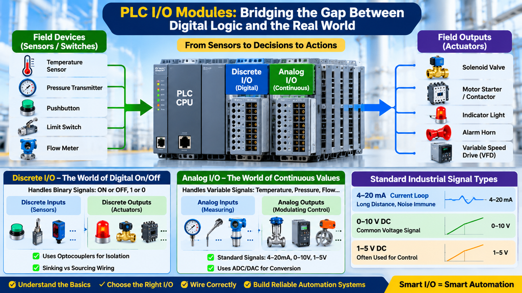
In modern industrial automation, the Programmable Logic Controller (PLC) serves as the digital brain of the facility. From automated assembly lines and chemical processing refineries to water treatment plants and power generation units, the entire operation relies on precise, high-speed, and reliable control. However, a PLC’s processor operates entirely in the digital realm—processing zeros and ones at ultra-low voltages (such as +5V DC logic levels).
The real physical world, on the other hand, is vast, messy, and continuous. Temperatures fluctuate smoothly, pressure vessels build up force gradually, fluid flow rates vary continuously, and safety gates either slam fully shut or swing wide open.
To bridge this fundamental gap between digital computation and physical reality, PLCs rely entirely on Input/Output (I/O) modules. Understanding how these modules function—specifically the distinct roles, wiring architectures, and applications of Discrete versus Analog I/O—is essential for any automation engineer, system integrator, or technical technician.
1. The PLC I/O Bridge: Connecting Code to Reality
Before diving into module types, it is helpful to visualize where I/O modules sit within the control ecosystem.
+-----------------------------------------------------------------------------------+
|                        THE PLC REAL-WORLD INTERFACE LOOP                          |
+-----------------------------------------------------------------------------------+
|  [ Field Devices ]  --->  [ I/O Modules ]  --->  [ PLC CPU / Image Table ]        |
|  (Sensors/Valves)         (Signal Conversion)    (Logic Execution)                |
+-----------------------------------------------------------------------------------+
When a field device changes state or measures a physical variable, that information must travel through the I/O interface before the CPU can evaluate it during the program execution phase. Conversely, when the PLC program determines that an action must occur (such as starting a motor or opening a valve), it writes that command to the output image table, which then commands the output module to energize the physical field device.
2. Discrete I/O Modules: The World of Digital On/Off
Discrete I/O (often referred to as digital I/O) deals with information that has only two distinct states: ON or OFF, True or False, 1 or 0. There are no shades of gray in discrete systems.
Common Discrete Field Devices
- Discrete Inputs (Sensors telling the PLC what is happening): Pushbuttons, selector switches, limit switches, photoelectric sensors, inductive proximity switches, and mechanical float switches.
- Discrete Outputs (Actuators controlled by the PLC): Solenoid valves, indicator pilot lights, audible horns/alarms, motor starter coils, and control relays.
How Discrete Modules Function
Internally, discrete modules use optocouplers (optical isolators) to provide complete galvanic isolation between high-voltage or noisy field circuits and the sensitive internal logic circuitry of the PLC.
When a field pushbutton is pressed, a voltage (typically 24V DC or 120V AC) is applied to the input terminal. The optocoupler detects this voltage and safely transmits an optical signal across an insulation barrier, toggling a bit in the PLC’s Input Image Table from 0 to 1.
Understanding Sinking and Sourcing in DC Discrete Wiring
One of the most critical aspects of installing discrete DC I/O modules is understanding current flow, commonly known as Sink vs. Source wiring:
- Sourcing Inputs/Outputs: Provide (source) positive current out to the field device. The common rail of the module is connected to DC Common (0V).
- Sinking Inputs/Outputs: Receive (sink) current flowing from an external power source through the field device. The common rail is connected to +24V DC.
Engineering Warning: Getting sink and source configurations mismatched will prevent field signals from registering or can cause input cards to fail under reverse-polarity conditions.
3. Analog I/O Modules: The World of Continuous Variables
While discrete modules handle binary conditions, Analog I/O modules process continuous signals that vary infinitely across a defined range.
Common Analog Field Devices
- Analog Inputs (Measuring physical parameters): Pressure transmitters, temperature sensors (thermocouples and RTDs), level sensors, flow meters, and vibration monitors.
- Analog Outputs (Modulating control elements): Variable Frequency Drives (VFDs) for motor speed control, proportional control valves, motorized dampers, and heating element controllers.
Standard Industrial Analog Signal Types
To ensure compatibility across different manufacturers (such as Siemens, Allen-Bradley, Schneider Electric, and ABB), analog signals are standardized into specific electrical ranges:
- Current Loops (4–20mA): The industry gold standard for long-distance industrial signal transmission. Because current is constant regardless of wire resistance over long cable runs, 4–20mA loops are exceptionally resilient to voltage drops and electrical noise. (Note: The “live zero” 4mA baseline allows the system to instantly detect a broken wire if the signal drops to 0mA).
- Voltage Signals (0–10V DC, 1–5V DC): Commonly used for short-distance signal routing inside clean control enclosures or between adjacent panel equipment.
Analog-to-Digital and Digital-to-Analog Conversion
Because a PLC CPU cannot natively process a raw 4–20mA electrical current, analog input modules contain specialized hardware called Analog-to-Digital Converters (ADCs).
- The Conversion Process: The ADC samples the incoming continuous electrical signal at regular intervals and translates it into a scaled digital integer value (for example, a 12-bit or 16-bit counts range such as 0 to 32,767).
- Engineering Scaling: The automation engineer then uses scaling instructions (such as SCP or linear scaling blocks in PLC software) to convert those raw counts back into engineering units—translating
6,553 countsinto a readable value like150.5 °Cor45.2 PSI. - Digital-to-Analog Conversion (DAC): Conversely, analog output cards use DACs to convert digital control numbers from the CPU into smooth 4–20mA output currents or 0–10V voltages to drive VFD speeds or valve positions.
4. Comprehensive Comparison: Discrete vs. Analog I/O
To help select the correct hardware architecture for your next control panel design, consider the following technical comparison:
| Feature / Metric | Discrete I/O Modules | Analog I/O Modules |
| Signal Nature | Binary (ON/OFF, True/False, 1/0) | Continuous variable across a range (e.g., 4–20mA) |
| Typical Field Devices | Pushbuttons, limit switches, solenoids, motor starters | Pressure transmitters, thermocouples, VFD speed references |
| Internal Processing | Direct bit-level mapping in the Input/Output Image Tables | ADC/DAC conversion scaled to engineering integer/real values |
| Wiring Requirements | Simple 2-wire switching cables or multi-conductor cords | Shielded twisted-pair cables to prevent Electromagnetic Interference (EMI) |
| Primary Engineering Focus | Sinking/sourcing DC configurations and interposing relays | Signal scaling, loop power supply, and noise grounding |
5. Panel Wiring and Signal Integrity Best Practices
Mixing discrete high-power circuits with sensitive analog signals inside an industrial control panel is a recipe for erratic machine behavior if proper guidelines are ignored.
- Electromagnetic Interference (EMI) Segregation: High-voltage AC power lines and noisy discrete inductive outputs (like large contactor coils) must be physically separated from low-voltage shielded analog signal cables inside wireways to prevent noise coupling and unstable sensor readings.
- Shield Grounding: Analog signal cable shields must be grounded at one end only (typically at the control panel chassis ground bar) to prevent ground loops that induce circulating currents and corrupt sensor accuracy.
- Interposing Relays: To protect expensive PLC digital output cards from inductive kickbacks when switching heavy inductive loads, always use interposing control relays.
6. Practical Field Checklist: I/O Commissioning Matrix
Use this field checklist during Factory Acceptance Testing (FAT), Site Acceptance Testing (SAT), or routine maintenance to verify your I/O infrastructure:
- [ ] Visual Hardware Inspection: Verify that all discrete and analog I/O cards are securely seated in their backplane slots and keyed correctly.
- [ ] Power Supply Verification: Check that auxiliary 24V DC sensor power supplies are stable and regulated before energizing field loops.
- [ ] Discrete Point-to-Point Test: Force digital input and output channels via the programming software to verify field wiring and device response.
- [ ] Analog Loop Calibration: Verify 4–20mA loop integrity using a precision multimeter, ensuring transmitter zero and span calibrations match PLC software scaling ranges.
- [ ] Shield Continuity Check: Confirm that all analog cable drain wires are securely terminated to the panel earth ground bar.
7. Conclusion
Mastering the distinction between discrete and analog I/O modules is the cornerstone of effective industrial automation engineering. While discrete modules manage the binary logic of start/stop commands and safety interlocks, analog modules provide the sensory feedback loop required for precise process control, temperature regulation, and speed modulation. By respecting proper wiring standards, understanding signal conversion, and maintaining rigorous panel hygiene, you ensure reliable, fault-tolerant industrial operations.
🚀 Accelerate Your Engineering Career with Free Documents Hub
Knowing how PLCs interface with the physical world is only half the battle; mastering modern industrial documentation, code compliance, and smart control frameworks is what sets top-tier engineers apart.
At Free Documents Hub, we offer specialized remote training programs covering industrial engineering design, PLC programming workflows, and technical documentation. Our programs are specifically designed to bridge the gap between academic theory and real-world shop-floor execution.
🛠️ Ready to elevate your technical credentials?