Fire Alarm Panel (FACP):
Types, Selection
and Programming
Conventional, addressable, and analogue addressable — the three FACP types explained, compared, and applied. Plus the complete programming process, cause and effect matrix, and address scheduling. Free Excel template included.
Table of Contents
- What Is a Fire Alarm Control Panel?
- The Three FACP Types — an Overview
- Conventional FACP — How It Works
- Addressable FACP — How It Works
- Analogue Addressable FACP — How It Works
- Side-by-Side Comparison
- How to Select the Right FACP
- The FACP Programming Process
- The Cause and Effect Matrix
- Device Address Scheduling
- Structure of the Excel Template
- Standards Alignment
- Free Download — Excel Template
- Conclusion
What Is a Fire Alarm Control Panel?
The Fire Alarm Control Panel (FACP) — also called the Fire Alarm Control Unit (FACU) in NFPA 72 terminology, or the Fire Alarm Control Equipment (FACE) in BS 5839 — is the brain of the fire alarm system. It is the central processing unit that receives signals from all detection devices, processes those signals against its programmed logic, determines whether an alarm condition exists, and activates the appropriate outputs — sounders, suppression systems, HVAC controls, lift interfaces, and emergency communications.
Everything else in a fire alarm system — detectors, manual call points, sounders, sprinkler interfaces, BMS connections — is peripheral equipment that either sends information to the panel or receives instructions from it. The quality, capability, and programming of the FACP determines the intelligence, reliability, and functionality of the entire system. A poorly specified or poorly programmed FACP can render an otherwise well-designed and well-installed fire alarm system ineffective — or worse, unreliable.
“The FACP is not simply a control box. It is the intelligence that determines how the building responds to fire. Every alarm decision, every output action, every fault response — all of it flows from the panel’s programming.”
The FACP must be specified, selected, and programmed by a qualified fire alarm engineer. It must comply with the applicable standard for the project — NFPA 72 in the United States and Middle East, BS 5839 in the UK and Commonwealth countries, EN 54-2 in Europe, and SAES-B-067 on Saudi Aramco facilities. The panel must be third-party certified to the applicable product standard — EN 54-2 for European markets, UL 864 for North American markets — before it can be installed on a compliant project.
The Three FACP Types — an Overview
Fire alarm control panels are divided into three fundamental types based on their detection architecture, their ability to identify the location and status of individual devices, and the intelligence embedded in the system. Understanding the difference between these three types is the foundation of correct fire alarm system specification.
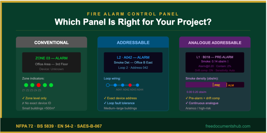
Conventional
Zone-based system. Multiple devices on each circuit. Alarm identifies the zone — not the individual device. Simplest and lowest cost. Suitable for small buildings.
NFPA 72 Style B · BS 5839 Class L/M · 10–20 devices per zone
Addressable
Loop-based system. Every device has a unique address. Alarm identifies the exact device and its location. Medium complexity. Suitable for most commercial and industrial buildings.
NFPA 72 Style 4/6 · EN 54-2 · 99–250 devices per loop
Analogue Addressable
Loop-based with continuous analogue reporting. Every device reports a real value — smoke density, heat level. Pre-alarm, drift compensation, full diagnostics. Required for high-risk and Aramco facilities.
NFPA 72 Style 6/7 · EN 54-2 · SAES-B-067 · 250–500 devices per loop
Conventional FACP — How It Works
A conventional fire alarm system divides the protected building into zones — typically one zone per floor, one zone per area, or one zone per defined space. Each zone is served by a dedicated two-wire circuit that runs from the FACP to the first device in the zone, through all subsequent devices in series, and terminates at an end-of-line resistor at the last device. All detectors and manual call points on the zone circuit are wired in parallel onto this two-wire loop.
When any device on the zone circuit activates — when a smoke detector triggers, or a manual call point is operated — the device changes its impedance on the circuit. The panel detects this impedance change and registers an alarm for that zone. The panel cannot determine which specific device caused the alarm. It knows only that something on Zone 03 has activated. The LED indicator on the detector itself illuminates locally, but without physical inspection of the zone, the exact device cannot be remotely identified.
Wiring and Fault Detection
Conventional zones are wired in a radial (star) configuration — each zone runs outward from the panel and does not return. This means that if the circuit is broken — by a cable fault, a damaged conduit, or a corroded termination — all devices beyond the break point are lost. The panel registers a zone fault, but the section of the zone beyond the fault cannot be monitored. This is the fundamental limitation of conventional wiring: a single cable fault can disable a portion of an entire zone’s detection coverage.
The end-of-line resistor serves as the panel’s circuit supervision mechanism. Under normal conditions, the panel measures a specific resistance value on the circuit — the combined impedance of the devices plus the end-of-line resistor. If this value changes significantly — because a cable is broken, a connection is corroded, or the resistor is missing — the panel registers a fault. This supervision is continuous and automatic.
When to Use a Conventional Panel
Conventional panels are appropriate for small, simple buildings where zone-level detection is sufficient — shops, small offices, residential properties, and small warehouses. The key question is: if an alarm sounds and the display shows “Zone 03,” does the building operator have a manageable search area to investigate? In a small building with ten devices per zone, Zone 03 might cover one floor of 200 square metres — a manageable investigation area. In a large building with twenty devices per zone covering a full floor of 2,000 square metres, zone-level identification is insufficient.
Addressable FACP — How It Works
An addressable fire alarm system replaces the zone circuit concept with a loop circuit — a single two-wire cable that leaves the panel, passes through each device in sequence, and returns to the panel, forming a complete loop. Each device on the loop has a unique address — a number from 001 to 250 (or higher, depending on the panel) — set at the device using rotary switches, DIP switches, or a programming tool before installation.
The panel communicates with every device on the loop individually, polling each address in rapid sequence — typically completing a full loop poll in less than one second. Each device responds to its poll with its current status: normal, alarm, fault, or isolated. Because every device has a unique address and the panel knows the status of each address individually, the panel can identify not just which zone but exactly which device — at which address, in which location — has activated or faulted.
Loop Integrity and Fault Tolerance
The loop wiring of an addressable system provides a significant reliability advantage over conventional radial wiring. Because the cable forms a complete loop — leaving the panel at one terminal and returning at another — a single open-circuit fault anywhere on the loop does not disable all devices. The panel detects the break and switches to a degraded mode, polling devices from both ends of the loop simultaneously. All devices except those immediately adjacent to the break point remain operational. This is described as Style 4 or Class B loop wiring in NFPA 72 terminology.
On Class A (Style 6 or 7) wiring — where the loop is fully supervised against both open-circuit and short-circuit faults — an isolator module is placed between groups of devices. When a short-circuit fault occurs, the isolator nearest to the fault activates automatically, disconnecting the faulty section while keeping the rest of the loop fully operational. The faulty section loses only the devices between the two nearest isolators — typically eight to fifteen devices — rather than the entire loop.
Programming and Intelligence
The addressable panel’s intelligence lies in its programming. Each address must be assigned a device type, a location description, and a zone. The panel’s cause and effect logic determines which outputs activate in response to which inputs. A sophisticated addressable panel can be programmed to activate specific sounders in specific areas, shut down specific HVAC units, recall specific lifts, and release specific door holders — all based on which exact device activated at which address in which zone. This level of targeted response is impossible with a conventional panel.
Analogue Addressable FACP — How It Works
The analogue addressable panel is the most sophisticated and most capable type of fire alarm control panel. It combines the device-level identification of the addressable system with a fundamentally different approach to detection: instead of devices that simply switch between normal and alarm states, analogue detectors continuously measure and report the actual physical quantity they are sensing — smoke density in obscuration per metre, temperature in degrees Celsius, carbon monoxide concentration in parts per million.
The panel receives this continuous stream of analogue values from every device on every loop, processes them against programmed thresholds, and makes alarm decisions based on the actual measured values rather than simple on/off switching. This enables capabilities that are impossible with conventional or standard addressable systems.
Pre-Alarm and Alert Levels
The most significant capability of the analogue system is pre-alarm — the ability to alert building management that smoke or heat levels are rising toward an alarm threshold before the full alarm is triggered. When a smoke detector’s analogue value crosses the alert threshold — typically set at 60 to 70% of the full alarm threshold — the panel generates a pre-alarm signal. This triggers a visual indication at the panel and may alert a control room operator, who can investigate the cause before the full alarm triggers and building evacuation begins.
Pre-alarm is critically important in environments where false alarms have significant consequences — data centres, clean rooms, hospitals, and industrial process facilities. An analogue system’s ability to detect and alert before triggering a full alarm dramatically reduces the frequency of unnecessary evacuations while maintaining the highest level of fire protection.
Drift Compensation and Self-Diagnostics
Over time, smoke detectors accumulate dust and contamination that changes their base sensitivity — a detector that was perfectly calibrated at commissioning may become increasingly sensitive as contamination accumulates, eventually generating false alarms from normal airborne dust. In a conventional or standard addressable system, this problem is only discovered when the false alarm occurs.
An analogue addressable detector continuously monitors its own contamination level and reports it to the panel. When contamination reaches a defined threshold, the panel generates a maintenance alert — the detector needs cleaning. Meanwhile, the panel automatically adjusts the detector’s alarm threshold to compensate for the contamination level, maintaining consistent detection sensitivity throughout the detector’s service life. This combination of predictive maintenance and automatic sensitivity compensation is one of the most practically valuable features of analogue technology.
Saudi Aramco and High-Risk Facility Requirements
SAES-B-067 — Saudi Aramco’s fire protection standard — requires addressable fire alarm systems as the minimum for all Aramco facilities, and analogue addressable systems for high-hazard process areas, refineries, and facilities where the consequences of a missed or delayed alarm are severe. The continuous analogue reporting, pre-alarm capability, loop fault tolerance, and self-diagnostic features of analogue addressable systems align directly with the high-reliability requirements of critical industrial infrastructure.
Side-by-Side Comparison
| Feature | Conventional | Addressable | Analogue Addressable |
|---|---|---|---|
| Detection Precision | Zone level only | Exact device address | Exact device + analogue value |
| Wiring Style | Radial — no loop return | Loop — returns to panel | Loop — Class A capable |
| Single Cable Fault | Disables part of zone | Degraded but operational | Isolators limit fault to small section |
| Pre-Alarm Capability | No | No | Yes — configurable thresholds |
| Drift Compensation | No | No | Yes — automatic |
| Contamination Detection | No | Limited | Yes — continuous monitoring |
| Cause & Effect Programming | Basic — zone level | Full — device level | Full — device + analogue level |
| Devices per Circuit | 10–20 per zone | 99–250 per loop | Up to 500+ per loop |
| Programming Complexity | Low — DIP switches | Medium — PC software | High — PC software + thresholds |
| Cost | Lowest | Medium | Highest |
| SAES-B-067 Compliance | Not acceptable | Minimum standard | Required for process areas |
| Typical Application | Small buildings <500m² | Medium–large commercial | Industrial, high-risk, Aramco |
How to Select the Right FACP
FACP selection is not a commercial decision — it is a technical and regulatory one. The correct panel type is determined by the building’s size and complexity, the regulatory standard applicable to the project, the client’s operational requirements, and the level of detection precision needed for the specific risk profile of the facility.
The Six Key Selection Questions
- How many devices? Under 100 — conventional may be sufficient. 100 to 500 — addressable. Over 500, or where maximum loop integrity is required — analogue addressable with multiple loops.
- Is exact device identification required? Any building where the operator or emergency services need to know which specific detector activated requires addressable or analogue addressable. This includes all buildings above a single storey and any building where the investigation area per zone exceeds a manageable size.
- Is a cause and effect matrix required? Any building with HVAC shutdown, lift recall, suppression release, or door holder outputs requires a programmable addressable or analogue addressable panel. Conventional panels cannot execute device-specific cause and effect logic.
- Is this a Saudi Aramco or major industrial facility? SAES-B-067 mandates addressable as the minimum. Confirm with the Aramco proponent engineer before specifying — some facilities require analogue addressable throughout.
- Is pre-alarm required? Only analogue addressable panels provide pre-alarm. Required in data centres, clean rooms, hospitals, and any facility where false alarms have severe operational consequences.
- What is the fire risk profile? High-risk occupancies — process industries, storage of flammable materials, facilities with sleeping occupants, healthcare — warrant analogue addressable regardless of building size.
The Common Specification Mistake
The most frequent FACP specification error is selecting a conventional panel for a building that is slightly too large or complex for conventional technology — typically a three to five storey office building with 80 to 120 devices. The conventional panel is specified because it is cheaper and the engineer is familiar with it. The result is a system where a Zone 02 alarm requires a physical search of an entire floor to identify the activated device, where cause and effect outputs cannot be targeted by device, and where a single cable fault disables a significant portion of the detection coverage. The additional cost of an addressable panel in this scenario is minor. The performance difference is significant.
The FACP Programming Process
Programming a fire alarm control panel is a structured technical process that must be carried out by a qualified commissioning engineer using the panel manufacturer’s approved software. It is not a task that can be delegated to an installation technician or performed without the approved design documents. Every programming decision — from zone descriptions to cause and effect logic — must be traceable to an approved design document.
Pre-Programming System Setup
Before any devices are addressedConnect the laptop to the panel via RS-232, USB, or Ethernet. Install and verify the panel software version matches the panel firmware. Create a new project file — project name, site address, engineer’s name. Configure the system type — conventional, addressable, or analogue — and the number of loops. Set the panel date, time, and access codes for all three access levels: operator, engineer, and manufacturer.
Device Address Programming
At each device — before installation or on siteSet the unique address at every device on the loop — detectors, MCPs, sounders, I/O modules, isolator modules — as per the approved device address schedule. For most addressable systems this is done using rotary dial switches on the device base or using a handheld programming tool. Each address must be unique on its loop and must match the address recorded in the approved address schedule. After all devices are installed, carry out a loop poll from the panel to confirm every address appears and no duplicates exist.
Zone Programming
In panel software — before cause and effectDefine all zones in the panel software — zone number, zone name (typically the location description: “Zone 01 — Server Room”), and floor or area. Assign every device address to its correct zone. Enter location text for every device address that will appear on the panel display when that device activates or faults. For analogue addressable systems, configure day and night sensitivity profiles for zones where sensitivity should change during cooking, cleaning, or low-occupancy hours.
Cause and Effect Matrix Programming
Only after approved cause and effect document is receivedProgram the complete cause and effect matrix — which input conditions activate which output actions. This is the most technically complex and consequential part of panel programming. Every output — general alarm, zone-specific sounders, AHU shutdown, lift recall, suppression release, BMS signal — must be correctly mapped to its triggering input condition. The programming must be verified against the approved cause and effect matrix document, which must be signed by the consultant or client before programming begins.
Analogue Sensitivity Programming
Analogue addressable panels onlyFor analogue addressable panels, program the sensitivity thresholds for each detector type — the alert level, the alarm level, and the contamination fault level. Configure drift compensation and day/night sensitivity profiles. Enable self-diagnostic features. Verify that analogue values are readable from the panel display for each device address — the commissioning engineer should be able to see the current smoke density or temperature reading for any device on any loop.
Verification, Upload, and Documentation
Final step — before commissioning testingReview the complete programming in the panel software before uploading. Upload to the panel and confirm successful transfer. Restart the panel and verify all devices appear with no unexpected faults. Save and back up the programming file — minimum two copies. Print the as-programmed documentation: zone schedule, address schedule, cause and effect matrix. This documentation becomes part of the handover package and must be signed by the commissioning engineer and witnessed by the client representative.
The Cause and Effect Matrix
The cause and effect matrix is the document that defines the system’s response logic — what happens in the building when a specific input condition occurs. It is the translation of the building’s fire safety strategy into the panel’s programming. Every output action in the building — every sounder activation, every HVAC shutdown, every lift recall, every suppression release — must be defined in the cause and effect matrix and verified in the panel programming.
The matrix is structured as a grid: rows represent input conditions (zone alarms, specific device activations, two-detector coincidence conditions), and columns represent output actions (sounder zones, HVAC circuits, lift groups, door holders, suppression systems, BMS signals). Each cell in the matrix contains either a tick — this output activates for this input — or a dash — this output does not activate.
Why the Matrix Must Be Approved Before Programming
The cause and effect matrix must be reviewed and approved by the fire safety consultant, the client, and in some cases the local fire authority — before the commissioning engineer programs it into the panel. This requirement exists because the matrix defines life-safety responses. An incorrect matrix entry — a suppression system released by the wrong zone, a lift not recalled during an alarm, an AHU that continues running and spreading smoke — can have fatal consequences.
⚠ Never Program the Cause and Effect Matrix Without an Approved Document
This is one of the most serious quality failures on fire alarm projects. A commissioning engineer who programs the cause and effect matrix based on their own interpretation of the design — without a formally approved matrix document — has made life-safety decisions that are beyond their authority. If the programmed logic is wrong, the responsibility falls entirely on the engineer who programmed it without authorisation. Always obtain a signed, approved cause and effect matrix document before programming begins.
Device Address Scheduling
The device address schedule is the controlled document that assigns a unique address to every device on every loop, records the device type and location description, and defines the zone assignment and sensitivity settings for each address. It is the programming bible — the document that the commissioning engineer uses to set addresses at devices, program the panel software, and verify that the installed system matches the approved design.
A well-structured address schedule contains the following information for every device: loop number, address number, zone assignment, device type, location description, drawing reference, day and night sensitivity mode, and current status. This schedule is a live document during installation — it must be updated immediately when any device is relocated, replaced, or re-addressed.
At handover, the final as-programmed address schedule — reflecting the system as actually installed and programmed — is submitted as part of the project close-out documentation. This document is used by every maintenance engineer who works on the system for the rest of its operational life. An inaccurate address schedule is a maintenance liability — it causes the wrong devices to be investigated, the wrong zones to be isolated, and the wrong programming changes to be made.
Structure of the Excel Template
| Sheet | Title | Content |
|---|---|---|
| Sheet 1 | Cover Page | FDH branded document — NFPA 72 / BS 5839 / EN 54-2 / SAES-B-067 reference |
| Sheet 2 | FACP Types Comparison | 11-parameter side-by-side comparison of Conventional, Addressable, and Analogue Addressable — architecture, detection precision, wiring style, fault tolerance, programming complexity, cost, and SAES-B-067 suitability |
| Sheet 3 | FACP Selection Guide | 12 building types with recommended panel type and key reason + 6 key selection questions with guidance |
| Sheet 4 | FACP Programming Checklist | 35 programming tasks across 6 sections — Pre-setup, Device Address, Zone Programming, Cause and Effect, Analogue Sensitivity, Verification — each tagged by panel type (All / Addr+Ana / Ana only) |
| Sheet 5 | Address Schedule | 20 sample device entries on Loop 1 and Loop 2 — address, zone, device type, location, sensitivity mode, day/night settings, status — auto summary with PASS/FAULT/Total count |
| Sheet 6 | Cause and Effect Matrix | 10 input conditions vs 10 output actions — ✓ / — grid showing which outputs activate for which inputs — sounders, AHU shutdown, gas valve cutoff, lift recall, suppression, BMS alarm signal |
Standards Alignment
NFPA 72 — National Fire Alarm and Signaling Code
NFPA 72 Chapter 23 addresses protected premises fire alarm systems, defining requirements for initiating devices, notification appliances, and control equipment. Chapter 10 addresses equipment and covers FACP certification and installation requirements. NFPA 72 defines circuit styles (Style A through Style 7) that determine the wiring configuration and fault tolerance requirements for both conventional and addressable systems. FACP equipment must be listed and labeled by a nationally recognised testing laboratory — typically UL or FM — confirming compliance with UL 864 or equivalent.
BS 5839 Part 1 — Code of Practice
BS 5839 Part 1 defines fire detection and alarm system categories — from Category L1 (full life protection) through Category M (manual only) — each with specific requirements for detection coverage and FACP capability. Category L1 and L2 systems require addressable or analogue addressable panels for buildings of any significant size. BS 5839 also defines the requirement for the fire alarm control panel to provide clear zone identification with location text and to support the building’s evacuation strategy through appropriate programming.
EN 54-2 — Fire Detection and Fire Alarm Systems: Control and Indicating Equipment
EN 54-2 is the European product standard for fire alarm control panels. A panel bearing the CE mark and EN 54-2 certification has been tested and approved to this standard by a notified body. EN 54-2 defines the functional requirements for alarm signalling, fault signalling, disablement, test facilities, and power supply monitoring. All fire alarm panels used on projects in Europe and many Gulf states must hold valid EN 54-2 certification.
SAES-B-067 — Saudi Aramco Fire Protection
SAES-B-067 requires addressable fire alarm systems for all Saudi Aramco facilities and analogue addressable systems for process areas and high-hazard applications. The panel must be listed to UL 864 or equivalent and must be from the Saudi Aramco Approved Vendors List (AVL). Programming must be submitted to the Saudi Aramco proponent engineer for review before commissioning. The cause and effect matrix must be approved by both the proponent and the fire safety consultant. As-programmed documentation must be submitted as part of the SATIP (Saudi Aramco Technical Inspection Procedure) package.
📥 Free Download — FACP Types & Programming Excel Template
6-sheet professional Excel template: FACP Types Comparison, Selection Guide, Programming Checklist (35 tasks), Address Schedule with 20 sample entries, and Cause & Effect Matrix. NFPA 72 / BS 5839 / EN 54-2 / SAES-B-067 aligned.
Conclusion
The fire alarm control panel is where every detection signal becomes a decision and every decision becomes a response. Specifying the wrong type — conventional where addressable is needed, addressable where analogue is required — produces a system that is installed, tested, and accepted, but fundamentally incapable of performing its life-safety function to the standard the building demands.
Understanding the difference between conventional, addressable, and analogue addressable panels — and the criteria that determine which is appropriate for each project — is foundational knowledge for every fire alarm engineer, installer, and project manager. The programming that follows the correct selection — address scheduling, zone definition, cause and effect logic — is what translates that hardware capability into a system that responds intelligently to the specific risks of the specific building it protects.
Download the free Excel template, use the comparison and selection guide to confirm the right panel type for your next project, complete the programming checklist systematically, and submit a cause and effect matrix that has been reviewed and approved before a single line of programming code is entered into the panel.
More Free Industrial Documents
Method statements, commissioning reports, NCR and RFI templates, cable schedules, FACP guides — all free, all available immediately.
Download Free FACP Template www.freedocumentshub.com