
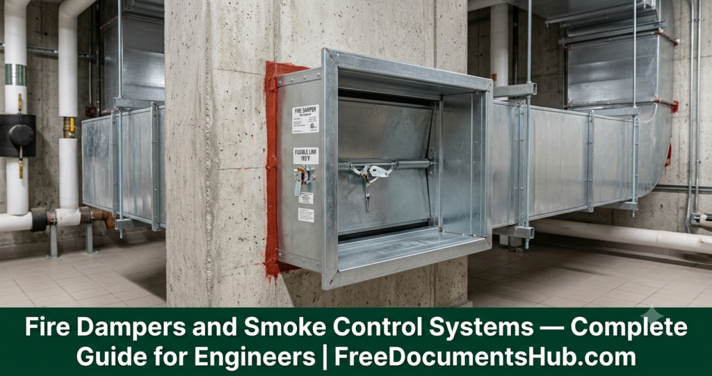
Fire dampers and smoke control systems are among the most critical and most frequently misunderstood components in building fire protection. Their purpose is not to extinguish fire — it is to prevent fire and smoke from spreading through a building’s ventilation and ductwork systems, protecting escape routes and giving occupants time to evacuate safely.
A correctly designed, installed, and maintained fire damper and smoke control system can be the difference between a contained fire and a building-wide catastrophe. An incorrectly installed or poorly maintained system provides false confidence — it looks correct but will fail at the moment it is needed most.
This guide covers everything engineers need to know — types, standards, design requirements, installation, testing, and maintenance.
Why Fire and Smoke Spread Through Ductwork
Modern buildings use extensive HVAC ductwork systems to distribute air throughout every area of a building. This same ductwork — which provides comfort and ventilation under normal conditions — becomes a direct pathway for fire and smoke to spread rapidly through fire-compartment walls and floors if it is not correctly protected.
A fire that begins in one room can spread toxic smoke throughout an entire building within minutes through unprotected ductwork penetrations. Smoke inhalation — not the fire itself — is the primary cause of death in building fires. Smoke control systems address this specific risk.
Types of Fire and Smoke Dampers
Understanding the difference between damper types is fundamental. Each type has a specific application and they are not interchangeable.
1. Fire Damper
A fire damper is installed where a duct penetrates a fire-rated wall, floor, or partition. Its purpose is to maintain the fire resistance rating of that element by closing automatically when exposed to heat — preventing fire from passing through the duct opening.
How it works: Fire dampers contain a fusible link — a heat-sensitive device that holds the damper blade in the open position during normal operation. When the surrounding air temperature reaches the rated temperature — typically 72°C for standard applications — the fusible link melts, releasing the spring-loaded blade which closes under spring tension.
Key classifications:
- Static fire damper — for use in systems where the fan stops on fire alarm activation. Blade closes on fusible link release only.
- Dynamic fire damper — for use in systems where the fan continues to operate during a fire. Rated to close against airflow without blade flutter or failure.
Temperature ratings:
- Standard: 72°C fusible link — general HVAC applications
- High temperature: 96°C or 260°C — for kitchen exhaust, boiler rooms, and high-temperature ductwork
Fire resistance ratings:
- E90 — maintains integrity for 90 minutes (smoke leakage not rated)
- EI60 / EI90 / EI120 — maintains both integrity and insulation for the rated period
2. Smoke Damper
A smoke damper is designed to prevent the passage of smoke — not fire — through ductwork during the early stages of a fire when temperatures may not be high enough to activate a fusible link.
How it works: Smoke dampers are motorised — they close on receiving an electrical signal from the fire alarm system or smoke detector. They do not rely on heat to activate. This is their critical advantage over fire dampers — they respond immediately when smoke is detected, before temperatures rise.
Applications:
- Supply and return air ducts serving smoke control zones
- Ducts penetrating smoke compartment boundaries
- Pressurisation system inlets and exhausts
- Stairwell pressurisation systems
Leakage classification (EN 1751):
- Class 1 — low leakage (most stringent)
- Class 2 — medium leakage
- Class 3 — high leakage
For smoke control applications — Class 1 or Class 2 leakage rating is required.
3. Combined Fire and Smoke Damper (FSD)
A combined fire and smoke damper performs both functions — it closes on smoke detection via motorised actuator AND maintains fire resistance via intumescent seals and rated construction.
This is the most commonly specified damper type for modern buildings where ductwork penetrates both fire-rated and smoke-compartment boundaries simultaneously.
Activation:
- Smoke signal from fire alarm — motorised actuator closes immediately
- Heat — intumescent seal expands, maintaining fire integrity if motor fails
Rating example: E600 S — fire integrity at 600°C, smoke leakage Class S (smoke rated)
4. Ceiling Radiation Damper
Installed in the ceiling above a lay-in tile ceiling where ductwork serves areas below. Prevents the radiant heat from a fire in the ceiling void from igniting materials in the occupied space below.
Application: Specifically for non-ducted return air ceiling systems — where air returns through the ceiling void rather than through return air ducts.
5. Corridor Damper
Installed in ductwork penetrating fire-rated corridor walls. Specific requirements apply — corridor dampers must be rated for the wall they penetrate and must not create a path for smoke to spread along the corridor — which is a primary means of escape.
Applicable Standards
Every fire protection engineer must know these standards:
| Standard | Title | Application |
|---|---|---|
| BS EN 15650:2010 | Ventilation for buildings — Fire dampers | Product standard for fire damper design, classification, and testing |
| BS EN 15727:2010 | Ventilation for buildings — Ducts and duct components — Smoke dampers | Product standard for smoke damper design, leakage classification |
| BS EN 1751:2014 | Ventilation for buildings — Air terminal devices — Aerodynamic testing | Leakage classification for smoke dampers |
| NFPA 90A | Standard for the Installation of Air-Conditioning and Ventilating Systems | Fire and smoke damper installation requirements — US and international projects |
| NFPA 92 | Standard for Smoke Control Systems | Complete smoke control system design, pressurisation, exhaust systems |
| NFPA 101 | Life Safety Code | Smoke compartmentation requirements, corridor protection |
| BS 9999:2017 | Fire safety in the design, management and use of buildings | UK fire strategy including smoke control requirements |
| CIBSE Guide E | Fire Engineering | Smoke control design methodology |
| SAES-B-067 | Saudi Aramco Fire Protection Standard | Aramco-specific requirements for smoke and fire damper installation |
| UL 555 | Standard for Fire Dampers | UL listing standard for fire dampers — required on US and many international projects |
| UL 555S | Standard for Smoke Dampers | UL listing standard for smoke dampers |
Design Requirements
Fire Compartmentation Principle
The starting point for any fire damper design is the building’s fire compartmentation strategy. A fire compartment is a space enclosed by fire-rated construction — walls, floors, and ceilings — that contains a fire for a defined period, preventing spread to adjacent compartments.
Every penetration of a fire compartment boundary — including ductwork — must be protected to maintain the compartment’s fire resistance rating. A 2-hour fire-rated wall with an unprotected duct penetration has an effective fire resistance of zero at that penetration.
Design rule: The fire resistance rating of the damper must equal or exceed the fire resistance rating of the wall or floor it penetrates.
Smoke Compartmentation
Smoke compartments are defined areas within a building designed to limit smoke spread. They are typically larger than fire compartments and are a critical component of the building’s life safety strategy — protecting escape routes from smoke contamination.
Every duct penetrating a smoke compartment boundary requires a smoke damper — or combined fire and smoke damper — rated for smoke leakage control.
Airflow Considerations
Static systems: Fan stops on fire alarm activation. Standard fire dampers are acceptable.
Dynamic systems: Fan continues to operate. Dynamic-rated dampers required — specified to close against the maximum airflow velocity in the duct. Critical for smoke control systems that use fans to pressurise stairwells or exhaust smoke.
Velocity limit: Most standard fire dampers are rated for velocities up to 10 m/s or 20 m/s. Exceeding the damper’s velocity rating causes blade flutter, noise, and potential failure to close.
Installation Requirements
Correct installation is as important as correct specification. A correctly rated damper installed incorrectly provides no protection.
Access for inspection and testing: Every fire damper and smoke damper must have a permanent, unobstructed access panel — minimum 300mm × 300mm — that allows visual inspection of the closed blade position and access for fusible link replacement and actuator maintenance. Installing a damper without access is a common and serious installation error that makes the required annual test impossible without destructive opening of the ceiling or wall finish.
Sleeve and mounting: Dampers must be installed in a sleeve that is correctly sized for the duct and correctly mounted in the wall or floor opening. The sleeve must be anchored independently of the duct — the damper must not be supported by the ductwork alone. Flexible connectors between ductwork and damper sleeve prevent building movement from transmitting stress to the damper.
Fusible link orientation: Fusible links must be installed in the correct orientation as specified by the manufacturer. An incorrectly oriented fusible link may not release correctly or may release at the wrong temperature.
Wiring — smoke and combined dampers: Motorised smoke dampers require electrical wiring from the fire alarm system. Wiring must be fire-rated cable — maintaining circuit integrity in a fire — to ensure the damper receives its closing signal even as fire develops. All wiring connections must be in accessible, labelled junction boxes.
Clearances: Damper blades require clearance to close fully. Insulation, fire stopping, or other materials must not obstruct the blade travel path. Post-installation check of full blade travel is mandatory before commissioning.
Testing and Commissioning
Pre-Commissioning Tests
Before the building is occupied — all fire and smoke dampers must be tested and the results documented.
Fire damper test (fusible link type):
- Manually release the fusible link — confirm blade closes fully and latches
- Reinstall a new fusible link — confirm blade holds open
- Check blade position indicator (where fitted) confirms open position correctly
Smoke damper test (motorised):
- Send smoke alarm signal from fire alarm panel — confirm damper closes within specified time (typically within 10 seconds of signal)
- Confirm position feedback signal returns to FACP — open and closed positions both confirmed
- Restore system — confirm damper reopens correctly on alarm reset
Combined damper test:
- Test motorised closure on smoke signal
- Test manual fusible link release for fire closure
- Confirm both functions independently operational
Annual Testing — NFPA 80 / BS 9999 Requirements
All fire and smoke dampers must be tested annually after installation. NFPA 80 requires:
- Each damper inspected and tested to confirm full closure
- Fusible links removed, inspected, and replaced
- Moving parts lubricated
- Results recorded — damper identification number, location, test date, result, tested by
The most common maintenance failure: Annual testing is not conducted. Dampers that have never been tested after installation are found seized open — blades corroded, fusible links degraded — completely non-functional. This is discovered only during the test that should have been conducted every year since installation.
Smoke Control System Types
Beyond individual dampers — complete smoke control systems use fans, dampers, and controls to actively manage smoke movement in a building during a fire.
Pressurisation Systems
A pressurisation system maintains a positive pressure differential in protected areas — typically stairwells, lobbies, and firefighter access routes — relative to adjacent fire-affected areas. This pressure differential prevents smoke from entering the protected space.
Stairwell pressurisation: The most common application. Supply fans inject fresh air into the stairwell, maintaining pressure above the fire floor. Smoke cannot enter the stairwell against this positive pressure. Design pressure differential: minimum 50 Pa across a closed door — NFPA 92.
Exhaust Systems
Exhaust systems remove smoke directly from the fire-affected area — reducing smoke density, improving visibility for occupants escaping, and improving conditions for fire brigade operations.
Atrium smoke exhaust: Large atria require engineered smoke exhaust systems that maintain a smoke-free layer at the occupant level during a fire. Roof-mounted exhaust fans remove smoke above the calculated smoke layer height.
Zoned Smoke Control
Large buildings are divided into smoke control zones. When a fire is detected in one zone — the supply to that zone is shut off (via smoke dampers) and exhaust is activated — preventing smoke from spreading to adjacent zones via the HVAC system.
Common Failures in Practice
Damper installed without access panel: Annual test cannot be conducted. Damper condition unknown. Building owner has no evidence of compliance. This is one of the most common deficiencies found during fire safety audits.
Fusible link not replaced after testing: Damper tested correctly — fusible link removed and not replaced. Damper blade drops and remains closed. HVAC system cannot operate. Or — blade left open with no fusible link — damper will never close on fire.
Motorised damper wired from normal power circuit: Power failure during fire cuts power to damper actuator. Damper cannot receive closing signal. Smoke spreads through uncontrolled ductwork.
Duct insulation blocking blade travel: Insulation applied after damper installation restricts blade movement. Blade cannot close fully. Fire resistance rating is void.
Wrong damper type installed: Static fire damper installed in a dynamic system. Fan continues to operate on fire alarm. Static damper blade cannot close against airflow. Damper remains open. Fire and smoke spread freely.
Download Free Fire Protection Documents
FreeDocumentsHub.com publishes professional engineering documents for fire protection engineers worldwide — ITPs, method statements, commissioning checklists, and inspection records.
Visit our Documents page for free downloads and our full premium library.
www.freedocumentshub.com — Available 24 Hours, 7 Days a Week
Published by FreeDocumentsHub.com — written by engineers with 19+ years of Gulf industrial project experience.