
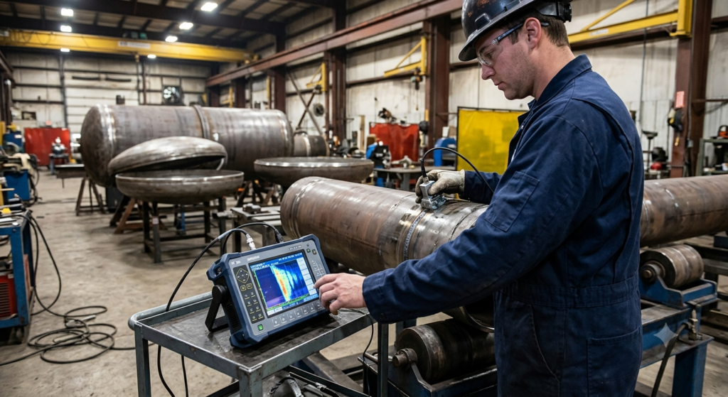
All NDT Methods in One Complete Guide — VT, PT, MT, RT, UT, PAUT, TOFD, ET, AE & LT
| Need NDT Documentation Ready for Audit? FreeDocumentsHub prepares WPS, PQR, ITP, MTR, and NDT procedure packages remotely for Saudi Aramco AVL, ASME, and oil & gas vendor registration. Free trial available. Order by WhatsApp, 24/7 turnaround. WhatsApp: Chat with our documentation team now → |
Every fabrication shop chasing Saudi Aramco AVL status, ASME code stamps, or oil and gas vendor pre-qualification eventually runs into the same wall: which non-destructive testing method actually applies to your weld, your material, and your code requirement? Inspectors, QA/QC engineers, and shop owners rarely need a semester of coursework — they need a working map of the ten methods that cover 95% of industrial inspection scope, and a way to know when each one is the correct call.
This guide walks through every major NDT method used in pressure vessel, piping, and structural fabrication — grouped the way ASME Section V and API inspection codes think about them: surface methods, volumetric methods, and specialized methods. Keep it as your working reference the next time a client, auditor, or code book asks ‘which method applies here?’
Why NDT Method Selection Matters for AVL & Code Compliance
Saudi Aramco’s Approved Vendor List process, ASME BPVC Section V, and API 510/570/653 inspection programs do not treat NDT methods as interchangeable. Each code section specifies which method is acceptable — or mandatory — for a given joint type, material thickness, and service condition. Selecting the wrong method, or documenting it incorrectly in your ITP and inspection reports, is one of the most common reasons AVL submittals and third-party audits get sent back for correction.
Getting the method selection and paperwork right the first time protects your project schedule and your vendor registration status. The rest of this guide gives you the technical grounding to make — and defend — that selection.
The NDT Method Family at a Glance
Before diving into each method, here is the full family in one table. Full technical detail, applicable standards, and selection guidance follow in the sections below.
| Method | Detects | Surface / Subsurface | Typical Materials |
| Visual (VT) | Surface flaws, fit-up, dimensional | Surface only | All materials |
| Liquid Penetrant (PT) | Surface-breaking cracks, porosity | Surface only | Non-porous metals, ceramics |
| Magnetic Particle (MT) | Surface & near-surface cracks | Surface & near-surface | Ferromagnetic materials only |
| Radiographic (RT) | Internal voids, porosity, inclusions | Volumetric | Most metals, some composites |
| Ultrasonic (UT) | Internal cracks, laminations, thickness | Volumetric | Most metals, some plastics |
| Phased Array UT (PAUT) | Internal flaws, sizing & mapping | Volumetric | Most metals |
| Time-of-Flight Diffraction (TOFD) | Crack height sizing, weld root flaws | Volumetric | Most metals |
| Eddy Current (ET) | Surface cracks, conductivity, coating | Surface & near-surface | Conductive materials |
| Acoustic Emission (AE) | Active/growing defects under load | Volumetric (global) | Pressure vessels, tanks, structures |
| Leak Testing (LT) | Through-wall leaks, seal integrity | Volumetric | Sealed vessels, piping systems |
Surface Methods
Surface methods find flaws that are open to, or very close to, the surface. They are typically the fastest and least expensive inspections, which is why almost every fabrication and welding standard requires at least one surface method before — or in addition to — volumetric testing.
Visual Testing (VT)
Visual testing is the foundation of every inspection program and the one method every welder, fitter, and QC inspector performs on nearly every joint. VT covers weld profile, undercut, overlap, surface porosity, misalignment, and dimensional conformance against the WPS and drawing.
- Standard reference: ASME Section V, Article 9; AWS D1.1 Clause 6
- Equipment: trained eye, mirrors, borescopes, weld gauges, and increasingly AI-assisted camera systems for repeatable documentation
- Limitation: cannot detect subsurface or embedded flaws — always paired with a volumetric method for code-critical joints
On the AI front: camera-based visual inspection tools are increasingly used to flag surface anomalies faster and more consistently than manual review alone. Positioned correctly, these tools augment the qualified inspector’s judgment call — they do not replace the code-mandated inspector sign-off or the certified NDT methods that follow.
Liquid Penetrant Testing (PT)
PT finds surface-breaking discontinuities — cracks, porosity, laps, and seams — in non-porous materials, including non-ferromagnetic metals like stainless steel and aluminum where MT cannot be used. A penetrant dye is applied, allowed to dwell and seep into surface openings, excess is removed, and a developer draws the trapped penetrant back out to form a visible indication.
- Standard reference: ASME Section V, Article 6; ASTM E165
- Best for: austenitic stainless steel welds, aluminum, non-magnetic castings
- Limitation: surface-breaking flaws only; surface must be clean and accessible; will not detect anything below the surface
Magnetic Particle Testing (MT)
MT is the ferromagnetic-material counterpart to PT. A magnetic field is induced in the part, and iron particles (dry powder or wet fluorescent suspension) are applied. Particles cluster at flux leakage points caused by surface and near-surface cracks, making the discontinuity visible.
- Standard reference: ASME Section V, Article 7; ASTM E709
- Best for: carbon steel and low-alloy steel welds, forgings, castings
- Limitation: ferromagnetic materials only — will not work on austenitic stainless steel or aluminum; flaw orientation relative to the magnetic field affects detectability, so two field directions are typically required
Volumetric Methods
Volumetric methods look through the full thickness of the material, finding internal flaws that surface methods cannot reach. These are the methods most frequently specified for pressure-retaining welds under ASME Section VIII and API piping codes.
Radiographic Testing (RT)
RT passes X-ray or gamma radiation through the part onto film or a digital detector. Internal voids, porosity, slag inclusions, and lack of fusion appear as density differences on the resulting radiograph — a permanent, highly regarded record that Aramco and third-party inspectors often specifically require for critical butt welds.
- Standard reference: ASME Section V, Article 2; ASME B31.3 for piping
- Strength: produces a permanent visual record; excellent for volumetric porosity and inclusions
- Limitation: radiation safety controls and exclusion zones required; less sensitive than UT for planar flaws like cracks oriented parallel to the radiation beam; film/digital processing adds turnaround time
Ultrasonic Testing — Conventional (UT)
Conventional UT sends high-frequency sound pulses into the material through a single-element transducer and reads the return echoes to locate internal reflectors — cracks, lack of fusion, laminations — and to measure remaining wall thickness in corrosion surveys. It is fast, portable, and does not require the radiation controls RT demands.
- Standard reference: ASME Section V, Article 4 and Article 5
- Strength: excellent for planar flaws (cracks, lack of fusion) that RT can miss; no radiation hazard; immediate results in the field
- Limitation: results depend heavily on operator skill and calibration; coarse-grained or highly attenuating materials (e.g., austenitic stainless welds) reduce reliability without special techniques
Phased Array Ultrasonic Testing (PAUT)
PAUT replaces the single transducer element with an array of small elements that can be electronically steered and focused, generating a real-time cross-sectional image of the weld volume instead of a single signal spike. This gives far better flaw sizing, positional accuracy, and a permanent digital record — which is why Aramco and many EPC specifications now favor PAUT over conventional UT for critical girth welds.
- Standard reference: ASME Section V, Article 4, Mandatory Appendix I; AWS D1.1 Annex
- Strength: superior flaw sizing and imaging; single scan covers multiple angles; strong digital documentation trail for audits
- Limitation: higher equipment cost and requires PAUT-specific operator certification beyond conventional UT Level II
Time-of-Flight Diffraction (TOFD)
TOFD uses a pair of transducers positioned on either side of the weld to detect the diffracted — rather than reflected — sound energy from the tips of a flaw. This makes it exceptionally accurate for measuring crack height through the wall thickness, which is critical input for fitness-for-service and fracture mechanics assessments.
- Standard reference: ASME Section V, Article 4, Mandatory Appendix III
- Strength: outstanding through-wall sizing accuracy; often paired with PAUT for a complete volumetric picture
- Limitation: dead zones near the top and bottom surface of the scan require a complementary method (typically PAUT or MT/PT) to cover fully
Specialized Methods
These methods fill gaps the core surface and volumetric techniques cannot cover — coating and conductivity checks, in-service defect growth monitoring, and pressure-boundary leak confirmation.
Eddy Current Testing (ET)
ET induces alternating current in a coil held near the part; changes in the resulting eddy currents reveal surface cracks, conductivity variations, coating thickness, and material sorting differences. It requires no couplant or consumables, making it fast for tube inspection in heat exchangers and condensers.
- Standard reference: ASME Section V, Article 8 and Article 26 (for heat exchanger tubing)
- Best for: heat exchanger and condenser tube inspection, surface crack detection on conductive materials, coating thickness verification
- Limitation: conductive materials only; limited penetration depth compared to UT/RT
Acoustic Emission Testing (AE)
AE is fundamentally different from the other methods — instead of sending energy into the part, sensors listen for the transient stress waves a growing defect emits while the structure is under load, typically during a pressure or proof test. It is a global monitoring technique, screening an entire vessel or pipeline in one test rather than scanning weld by weld.
- Standard reference: ASME Section V, Article 12; ASTM E1067 for FRP vessels
- Best for: pressure vessel and storage tank proof testing, in-service structural health monitoring
- Limitation: identifies that a defect is active and roughly where — follow-up with UT, RT, or PAUT is required to characterize and size it
Leak Testing (LT)
LT confirms the pressure boundary integrity of a sealed system using methods ranging from simple pressure-decay and bubble testing to sensitive helium mass-spectrometer and halogen-diode detection for high-reliability service. It is the final confirmation that fabrication and welding quality translates into a leak-tight vessel or piping system.
- Standard reference: ASME Section V, Article 10
- Best for: final acceptance testing of pressure vessels, piping systems, and tanks before commissioning
- Limitation: confirms there is a leak path but does not by itself characterize the underlying flaw — RT or UT is needed if a leak is found and root cause is required
How to Choose the Right Method
In practice, method selection is driven by four questions, in this order:
- What does the governing code or client specification require? Aramco engineering specifications, ASME Section VIII, and API piping codes often mandate a specific method for a specific joint class — this overrides personal preference.
- What is the material? Ferromagnetic materials open up MT; non-magnetic and austenitic materials push you to PT; conductive tubing favors ET.
- Is the flaw of concern surface-breaking or embedded? Surface concerns point to VT/PT/MT; internal concerns require RT, UT, PAUT, or TOFD.
- What is the consequence of a missed flaw? Critical, high-consequence joints (Category A/B pressure welds, sour service piping) typically call for a combination of methods — for example RT plus PT, or PAUT plus TOFD — rather than a single technique.
| Selection Shortcut Surface + accessible + ferromagnetic → MT Surface + accessible + non-magnetic → PT Internal + need permanent record → RT Internal + need precise sizing → PAUT + TOFD In-service + monitoring under load → AE Final pressure-boundary confirmation → LT |
Certification Pathway for NDT Personnel
Performing and signing off these methods requires qualified personnel under a recognized scheme. ASNT SNT-TC-1A and CP-189, along with CSWIP and PCN certifications common across Gulf-region projects, define Level I, II, and III competency for each method. Aramco vendor packages and third-party inspection agencies will check certification currency and scope as part of any AVL or project-specific inspector approval — a gap here stalls approval as often as a missing procedure does.
We cover the certification landscape — CWI, CSWIP, ASNT, and API inspector routes — in detail in our Friday training series. If you are building out an in-house NDT team or need your certifications validated for an Aramco submittal, that is a natural next read.
Where Documentation Fits In
Every method in this guide only counts toward AVL or code compliance if it is backed by the right paperwork: an Inspection and Test Plan (ITP) that specifies which method applies at which hold point, NDT procedures qualified to the applicable code, and traceable reports tied back to the WPS, PQR, and material test reports (MTR) for the joint in question. This is exactly the documentation package FreeDocumentsHub prepares remotely for fabrication shops pursuing Aramco AVL, ASME certification, and oil and gas vendor registration.
| Get Your NDT & Welding Documentation Package Prepared WPS, PQR, ITP, MTR, and MDR packages — prepared remotely, reviewed against your target code and client specification. Free trial. WhatsApp ordering, 24/7 availability. WhatsApp: Start your free trial today → |