
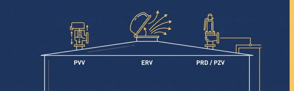
| In this article: What Pressure-Vacuum Vents (PVVs), Emergency Relief Vents (ERVs), and Pressure Relief Devices (PRDs/PZVs) do on atmospheric and low-pressure storage tanks, the standards that govern their design and sizing (API 650, API 2000, API 520/521, ASME Section VIII), and how field engineers verify these devices during site walk downs at operating refinery and petrochemical facilities. |
Storage tanks look static from the outside — a fixed steel shell holding a fixed volume of product. But internally, every atmospheric and low-pressure storage tank is in constant motion: pressure and vacuum inside the vapor space shift continuously as the tank fills, drains, and responds to temperature changes throughout the day. Left unmanaged, that shifting pressure can rupture a tank roof outward or collapse its shell inward — either one a serious safety and environmental incident. Pressure/vacuum relief systems exist to prevent exactly that, and they’re some of the most inspected, most standards-driven equipment on a tank farm.
Why Tanks Need Pressure and Vacuum Relief
Three everyday operating conditions drive pressure changes inside a storage tank’s vapor space:
- Thermal breathing — as ambient temperature rises during the day, vapor inside the tank expands and pressure builds; as temperature falls overnight, vapor contracts and pressure drops.
- Filling and draining — pumping product into a tank displaces vapor and raises internal pressure; draining product does the opposite, pulling the tank toward vacuum.
- Emergency exposure — external fire near a tank rapidly heats the contents, generating vapor far faster than normal breathing venting can handle.
None of these are unusual or abnormal events — they happen every single day on an operating tank. The relief system’s job is to accommodate all three without letting internal pressure or vacuum exceed what the tank shell was designed to withstand. Get it wrong, and the consequences are severe: overpressure can rupture the tank roof or shell, while excessive vacuum can cause the tank to visibly implode — a failure mode that has occurred on real sites when venting was blocked, undersized, or iced over.
The Three Layers of Protection
Pressure-Vacuum Vents (PVVs)
PVVs are the everyday workhorses of tank venting. They’re mechanical valves — sometimes weight-loaded, sometimes pilot-operated — set to open at a defined pressure and a defined vacuum threshold, handling routine breathing venting from thermal cycling and normal filling/draining operations. Under normal conditions, a PVV opens briefly to relieve pressure or admit air to relieve vacuum, then reseats, all without any operator intervention.
Emergency Relief Vents (ERVs)
ERVs are sized for a very different scenario: fire exposure. When a tank is exposed to external fire, the contents heat up and generate vapor at a rate that dwarfs normal breathing loads. ERVs are large-capacity devices — often weight-loaded manway covers or large-diameter relief hatches — designed to open fully and vent that emergency vapor load fast enough to protect the tank shell from catastrophic overpressure during a fire event.
Pressure Relief Devices (PRDs/PZVs)
On tanks connected to a shared flare or vapor recovery header — rather than venting directly to atmosphere — PRDs and pressure/vacuum relief valves (PZVs) route released vapor into that shared header for controlled disposal. Instead of an open atmospheric release, vapor is safely collected and directed to a flare or recovery system, reducing both emissions and fire risk at the tank itself.
Together, these three layers mean a tank is protected for its everyday breathing loads, for a worst-case fire scenario, and for controlled, low-emission disposal of whatever vapor is released — rather than depending on a single device to do all three jobs.
The Standards Behind the Design
Tank relief systems aren’t sized by rule of thumb — they’re governed by a specific stack of API and ASME standards, and reviewers expect to see that basis referenced in the documentation:
- API 650 — governs the design and construction of welded steel storage tanks, including the shell and roof design the relief system is ultimately protecting.
- API 2000 — the primary standard for venting atmospheric and low-pressure storage tanks, covering both normal (breathing) and emergency venting requirements and the calculation methods used to size them.
- API 520/521 — governs the sizing, selection, and installation of pressure-relieving systems more broadly, and provides the guidelines used to design and evaluate shared flare and relief header systems.
- ASME Section VIII — the pressure vessel design code, referenced for the pressure ratings of relief devices themselves.
A relief device’s nameplate — its set pressure, capacity, and tag number — exists because of these standards, and every one of those values needs to trace back to a calculation, not a guess.
Field Verification: Where the Documentation Meets Reality
Engineering drawings and P&IDs show what a relief system is supposed to look like. Field verification confirms what’s actually installed — and on an operating site, those two things don’t always match.
At an active refinery or petrochemical facility — a site like Petro Rabigh, for example — field engineers conduct physical walkdowns of every PVV, ERV, and PRD/PZV on the tank farm. For each device, the walkdown records the tag number, nameplate data (manufacturer, model, set pressure, capacity), and — where testing records exist — the last calibration set pressure. That field data is then checked against what the P&ID shows for that tag: same device, same set pressure, same connection point.
This isn’t a paperwork exercise. The verified field data feeds directly into engineering studies — conducted per API 520/521 and API 2000 — that assess whether a shared flare header has enough total capacity to safely handle the combined relief load from every tank connected to it. If a tank’s actual installed relief device doesn’t match what the header sizing calculation assumed, the header could be undersized for a real emergency scenario without anyone realizing it until the walkdown catches the discrepancy.
The Real Challenges Field Teams Run Into
Verification work sounds straightforward on paper — go to the tank, read the nameplate, compare it to the drawing. In practice, it’s rarely that clean:
- Corroded or illegible nameplates — years of weather exposure can leave a nameplate impossible to read without close inspection, cleaning, or cross-referencing manufacturer records.
- Tag mismatches — the tag number on the installed device doesn’t always match what the current P&ID revision shows, often because of undocumented replacements or maintenance-driven swaps over the years.
- Limited site support — walkdowns often happen with minimal operations support, meaning field engineers need to work methodically and independently rather than relying on someone on-site to confirm details.
None of these are excuses to guess. A mismatched tag or an unreadable set pressure gets flagged, investigated, and resolved with the same rigor as any other data point feeding into a flare header capacity study — because the consequence of an incorrect assumption isn’t a paperwork error, it’s a safety system that may not perform as designed during an actual emergency.
Why This Documentation Matters
Pressure/vacuum relief systems sit exactly at the intersection of routine operation and worst-case emergency response — which is why the documentation trail around them is held to a high standard. A complete package for this equipment typically includes a Datasheet referencing the governing API/ASME basis, a Method Statement for installation and field verification, a Risk Assessment covering the hazards specific to tank venting work, an ITP with hold points for set-pressure verification and nameplate confirmation, and a Checklist for the physical walkdown itself.
That’s the same document structure used across EPC and QA/QC submittals more broadly — and it applies just as directly to tank relief systems as it does to rotating equipment or electrical systems.
Need Documentation for a Tank Relief or Venting System?
If your project needs a Data sheet, Method Statement, Risk Assessment, ITP, or Checklist built around PVVs, ERVs, PRDs/PZVs, or a shared flare header verification scope, we can prepare it to match your project’s tag numbering and standard. Email contact@freedocumentshub.com — first correction or trial document is free, and we’re available 24/7.
This article is intended as general technical background on tank venting systems and does not replace project-specific engineering calculations or a qualified engineer’s sizing review.
Looking for ready-made EPC and QA/QC documentation for your next project? FreeDocumentsHub.com offers editable Data sheets, Method Statements, Risk Assessments, ITPs, Checklists, and sizing calculators for a wide range of oil & gas and industrial equipment — instant download, ready to customize for your project. Browse the full catalog below.