Which One Does Your Weld Actually Need?
Every pressure vessel weld has a story. It may look clean on the surface — smooth bead, no visible cracks, solid color. But inside that weld, defects can hide. Porosity. Slag inclusions. Lack of fusion. Cracks that are not visible to the naked eye but are wide enough to cause a catastrophic failure under pressure.
That is exactly why Non-Destructive Testing (NDT) exists — and why ASME Section VIII, Division 1 mandates it.
But here is the question fabrication workshops consistently struggle with: which NDT method do you actually need, and when?
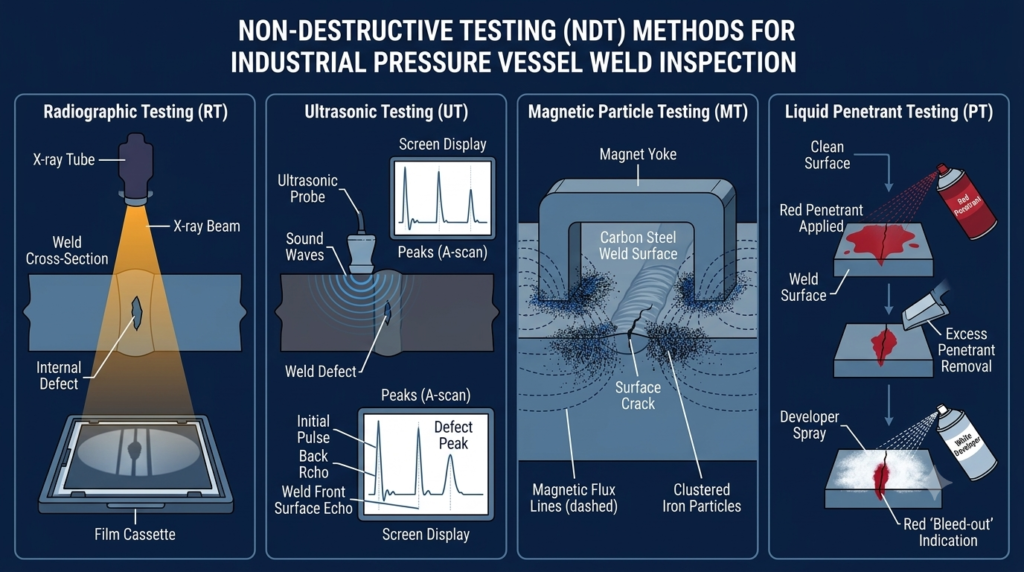
There are four primary NDT methods used in ASME pressure vessel fabrication: Radiographic Testing (RT), Ultrasonic Testing (UT), Magnetic Particle Testing (MT), and Liquid Penetrant Testing (PT). Each has a specific purpose, a specific code reference, and a specific type of defect it is designed to find.
Choosing the wrong method — or skipping one entirely — does not just put you at risk of a failed inspection. It puts the vessel, the operator, and your U Stamp certification at risk.
This guide breaks down all four methods in plain language so your team can make the right call every time.
Why NDT Is Non-Negotiable Under ASME Section VIII
Before we look at each method individually, it helps to understand why NDT is a code requirement — not a suggestion.
ASME Section VIII, Division 1 is the standard governing the design, fabrication, inspection, and testing of unfired pressure vessels. It defines minimum requirements for weld quality, material traceability, and examination methods based on the service conditions of the vessel.
Paragraph UW-11 of Section VIII specifically addresses the radiographic and ultrasonic examination of welds. It classifies vessels into different examination categories based on joint efficiency, and that classification directly determines what NDT is required.
Here is what drives the NDT requirement in practice:
- Joint efficiency factor: Higher joint efficiency (e.g., E=1.0) requires full radiographic or ultrasonic examination of all butt welds. This allows thinner walls and reduced material cost — but demands full NDT compliance.
- Material type and thickness: Certain materials and thicknesses require specific examination methods. Carbon steel responds to magnetic particle testing; austenitic stainless steel does not.
- Service conditions: Vessels intended for lethal service require 100% radiographic examination of all butt welds regardless of joint efficiency.
- Fabricator category: ASME U Stamp certification requires that your Quality Control System (QCS) documents which NDT methods are used, who performs them, and how results are recorded.
| Key Point: If your shop is U Stamp certified or working toward certification, your QCS must specify your NDT procedures, the qualifications of your examiners, and how you handle defect reporting and repair. NDT is not a bolt-on step at the end of fabrication — it is woven into your entire quality program. |
The Four Primary NDT Methods — What Each One Actually Does
1. Radiographic Testing (RT)
How It Works
Radiographic testing uses ionizing radiation — either X-rays or gamma rays — to penetrate the weld and project an image onto a film or digital detector on the other side. Defects inside the weld appear as density variations on the resulting radiograph. A trained Level II or Level III RT examiner interprets the image against ASME acceptance criteria.
What It Finds
- Porosity (gas pockets)
- Slag inclusions
- Incomplete fusion
- Incomplete penetration
- Cracks (primarily linear defects oriented in the beam direction)
What It Misses
RT is poor at detecting tight planar defects (like tight cracks) that are oriented parallel to the radiation beam. It also requires access to both sides of the weld — one side for the source, one for the film — which limits its use on complex geometries.
ASME Code Reference
- ASME Section V, Article 2 — Radiographic Examination
- ASME Section VIII, UW-51 — Radiographic Examination of Welds
- ASME Section VIII, UW-11 — Examination categories and requirements
When RT Is Required
Full RT is mandatory for:
- All butt welds in vessels designed with a joint efficiency factor of E=1.0
- All welds in vessels intended for lethal service (per UW-2)
- Category A and B butt welds above certain pressure-thickness thresholds
| Workshop Reality: RT requires a licensed radiography source, controlled exclusion zones, and trained personnel with valid certifications. If your shop does not have an in-house RT capability, you need a qualified third-party RT provider in your approved vendor list — and that provider must be referenced in your QCS. |
2. Ultrasonic Testing (UT)
How It Works
Ultrasonic testing introduces high-frequency sound waves into the weld through a transducer. When the sound wave encounters a defect, it reflects back to the transducer. The time delay and amplitude of the return signal allow the examiner to locate and size the defect. UT can be performed using conventional pulse-echo, Time-of-Flight Diffraction (TOFD), or Phased Array Ultrasonic Testing (PAUT).
What It Finds
- Planar defects — cracks, lack of fusion, incomplete penetration — which RT can miss
- Volumetric defects — porosity, slag inclusions
- Wall thickness measurement (critical for corrosion assessment)
- Disbonding in cladded or lined vessels
What It Misses
UT can struggle with very thin material sections (typically below 6mm). The skill of the examiner is also a significant variable — UT interpretation requires strong Level II or III competency.
ASME Code Reference
- ASME Section V, Article 4 — Ultrasonic Examination (Manual)
- ASME Section V, Article 5 — Ultrasonic Examination of Welds Using Phased Array
- ASME Section VIII, UW-53 — Ultrasonic Examination as Alternative to RT
When UT Is Preferred
- Thick-wall vessels (typically above 38mm wall thickness) where RT becomes impractical
- Complex geometries where RT access is physically impossible
- When PAUT or TOFD is used to replace RT under UW-53
- Nozzle welds and transition joints with changing wall geometry
| Important: ASME Section VIII UW-53 allows ultrasonic examination to be substituted for radiographic examination for butt welds, provided the UT procedure is qualified per Section V and the examiner holds valid UT Level II or III certification. This is increasingly common in modern shops using PAUT. |
3. Magnetic Particle Testing (MT)
How It Works
Magnetic particle testing is used exclusively on ferromagnetic materials (carbon steel, low-alloy steel, some stainless steels with sufficient ferrite content). The part is magnetized, and iron particles — either dry powder or suspended in a liquid — are applied to the surface. At a crack or surface discontinuity, the magnetic field leaks and the particles cluster, forming a visible indication.
What It Finds
- Surface cracks
- Near-surface cracks (typically within 6mm of the surface)
- Laps, seams, and cold shuts
- Toe cracks in fillet welds
What It Misses
MT cannot detect sub-surface or through-wall defects beyond its depth limit. It is also completely ineffective on non-ferromagnetic materials such as austenitic stainless steel (304, 316), aluminum, copper, and titanium.
ASME Code Reference
- ASME Section V, Article 7 — Magnetic Particle Examination
- ASME Section VIII, Appendix 6 — Magnetic Particle Examination
When MT Is Used
- Surface examination of carbon steel and low-alloy steel pressure vessel welds
- Examination of fillet welds, nozzle attachments, and support welds
- Post-weld heat treatment (PWHT) inspections to detect reheat cracking
- In-service inspections and fitness-for-service assessments
| Practical Note: MT is fast and cost-effective for carbon steel surface inspection. Many fabrication shops use it as a routine post-weld check on structural and support welds that do not require volumetric examination. It is also the most portable of the four methods — useful in field conditions. |
4. Liquid Penetrant Testing (PT)
How It Works
Liquid penetrant testing works on a simple principle: a low-viscosity liquid (the penetrant) is applied to the surface and allowed to seep into open surface defects by capillary action. After a set dwell time, excess penetrant is removed. A developer is then applied, which draws the penetrant back out of the defect and makes it visible — either visually (color contrast) or under UV light (fluorescent).
What It Finds
- Surface-breaking cracks
- Porosity open to the surface
- Laps, seams, and cold shuts at the surface
- Any discontinuity that breaks the surface and is open enough to accept the penetrant
What It Misses
PT detects surface defects only. It will not find sub-surface or through-wall defects. It is also ineffective on porous or rough surfaces where penetrant entrapment would produce false indications.
ASME Code Reference
- ASME Section V, Article 6 — Liquid Penetrant Examination
- ASME Section VIII, Appendix 8 — Liquid Penetrant Examination
When PT Is Used
- Non-ferromagnetic materials — austenitic stainless steel, duplex stainless, aluminum, titanium, copper alloys
- Any material where MT is not applicable
- Surface examination of root pass in single-sided welds before fill and cap passes
- Post-repair verification after grinding out defects
| Key Difference from MT: PT works on any material — ferromagnetic or not. MT is faster and gives better depth penetration for carbon steel. When in doubt on material type, PT is the safer universal choice for surface examination. When you need depth, combine PT with UT. |
At-a-Glance Comparison: RT vs UT vs MT vs PT
| NDT Method | What It Detects | Surface or Sub-Surface | Weld Applicable? | ASME Code Reference |
| RT (Radiographic Testing) | Volumetric defects: porosity, slag, incomplete fusion | Sub-surface (through-wall) | All welds — butt joints preferred | ASME Sec. V Art. 2; Sec. VIII UW-51 |
| UT (Ultrasonic Testing) | Planar & volumetric defects, wall thickness measurement | Sub-surface (through-wall) | All welds, complex geometries | ASME Sec. V Art. 4, 5; Sec. VIII UW-53 |
| MT (Magnetic Particle Testing) | Surface & near-surface cracks, laps, seams | Surface + ~6mm depth | Ferromagnetic materials only | ASME Sec. V Art. 7; Sec. VIII Appendix 6 |
| PT (Liquid Penetrant Testing) | Open-to-surface defects only | Surface only | Any material — ideal for austenitic SS, aluminum | ASME Sec. V Art. 6; Sec. VIII Appendix 8 |
How to Select the Right NDT Method for Your Weld
The right NDT method depends on four variables: the material, the weld type, the defect type you are searching for, and what ASME Section VIII requires for your vessel category. Here is how to work through the decision:
Step 1: Identify Your Material
- Carbon steel or low-alloy steel → MT or PT for surface; RT or UT for volumetric
- Austenitic stainless steel (304, 316, 317) → PT for surface (not MT); UT or RT for volumetric
- Duplex stainless steel → PT for surface; UT preferred for volumetric (RT also used)
- Non-metallic or composite → PT or UT depending on configuration
Step 2: Identify the Weld Type
- Butt weld in shell or head → RT or UT (volumetric required per UW-11 for E=1.0 vessels)
- Fillet weld (nozzle, support, lug) → MT or PT (surface only, no volumetric required by code for fillet welds unless specified)
- Full-penetration nozzle weld → MT or PT for surface; UT for volumetric if required by design
- Repair weld → PT or MT for surface plus UT per applicable code section
Step 3: Identify What You Are Looking For
- Sub-surface volumetric defects (porosity, slag) → RT or UT
- Planar sub-surface defects (cracks, lack of fusion) → UT preferred (RT less sensitive to planar defects)
- Surface and near-surface defects on carbon steel → MT
- Surface defects on any material → PT
Step 4: Check Your ASME Design Category
- Joint Efficiency E=1.0 → Full RT or UT on all butt welds (UW-51 or UW-53)
- Joint Efficiency E=0.85 → Spot RT on butt welds (UW-52)
- Joint Efficiency E=0.70 → No radiographic examination required on butt welds
- Lethal service → 100% RT of all butt welds regardless of joint efficiency (UW-2)
NDT Selection Decision Matrix
Use this reference table when specifying NDT on your weld procedures and fabrication data reports:
| Scenario | Recommended NDT Method |
| Butt weld in carbon steel pressure vessel, full radiography required | RT (per UW-51) — mandatory if design calls for full RT |
| Nozzle weld in SA-516 Gr. 70 carbon steel shell | MT for surface defects + UT for volumetric examination |
| Austenitic stainless steel weld (304L, 316L) | PT for surface + UT for sub-surface (RT also acceptable) |
| Thick-wall vessel (>38mm) — RT limited by geometry | UT — TOFD or phased array preferred for thick sections |
| Fillet weld on support lug or saddle | MT or PT depending on material; UT for toe cracks |
| Post-repair weld on in-service vessel | PT or MT (surface) + UT (volumetric) per repair code |
| Heat exchanger tube-to-tubesheet weld | PT for visual confirmation of root pass; UT for final |
| Clad or overlaid surface — disbonding concern | UT (straight beam) for bond integrity verification |
Personnel Qualification and Documentation Requirements
Under ASME Section VIII, it is not enough to perform NDT — it must be performed by qualified personnel and documented in a way that becomes part of the vessel’s data package. Here is what your QCS and fabrication records need to cover:
Examiner Qualification
- All NDT examiners must hold valid Level II or Level III certification under SNT-TC-1A (Recommended Practice for Personnel Qualification and Certification in Nondestructive Testing) or an equivalent standard accepted by ASME.
- Level II is the minimum required to perform and interpret NDT results independently.
- Level III may be required to approve procedures, qualify methods, or review final reports depending on your QCS structure.
- Certifications must be current, documented, and available for review by the Authorized Inspector (AI).
Written Procedure Requirements
Every NDT method used in your shop must be covered by a written procedure that meets the requirements of the applicable ASME Section V article. For example:
- RT procedures must define source type, film type, IQI (Image Quality Indicator) selection, exposure geometry, and acceptance criteria.
- UT procedures must define transducer frequency, search unit, coupling medium, scanning patterns, calibration blocks, and recording thresholds.
- MT procedures must define the magnetization technique, particle type, and light intensity requirements.
- PT procedures must define penetrant type, dwell time, developer type, and lighting conditions.
Documentation in the Data Package
The following NDT records must be included in your ASME Data Report package (Form U-1 and supporting documents):
- NDT reports for each examination performed, signed by a qualified examiner
- Reference to the written procedure used
- Identification of the weld joint examined (joint number, seam designation)
- Results and disposition (acceptable or rejected; if rejected, what repair was made and what re-examination confirmed acceptance)
- Examiner name, certification level, and certification expiration date
| Authorized Inspector Role: Your Authorized Inspector (AI) from your ASME-recognized Inspection Agency will review NDT records as part of final vessel certification. Incomplete, missing, or improperly signed NDT reports are one of the most common reasons for certification delays. Build your documentation habits correctly from the first weld. |
Common NDT Mistakes That Fail ASME Inspections
Based on what consistently trips up fabrication workshops during U Stamp audits and vessel inspections, here are the mistakes to avoid:
Using MT on Austenitic Stainless Steel
Magnetic particle testing does not work on non-ferromagnetic materials. Grade 304 and 316 stainless steel are austenitic — they have no significant ferromagnetic response. Applying MT to these welds produces no meaningful result and creates false confidence. Use PT for surface examination of austenitic stainless welds.
Relying on RT Alone for Thick-Section Welds
RT sensitivity decreases significantly in thicker sections. For walls above approximately 38mm, conventional film RT may not provide adequate detection of planar defects. PAUT or TOFD provides far superior characterization of thick-section weld integrity. The code allows UT as a substitute for RT under UW-53 — use it when geometry and thickness call for it.
Skipping the Written Procedure
Every NDT method must be backed by a written procedure that references the applicable ASME Section V article. Performing NDT without a formally documented and approved procedure is a non-conformance under your QCS. The AI will ask to see your procedures during the inspection — have them ready.
Under-Qualified Personnel Performing Examination
A Level I examiner can assist in performing NDT but cannot independently interpret results or sign off on reports. Only Level II or III personnel can make final accept/reject decisions and sign examination reports. Verify certification levels before assigning personnel to ASME-required examinations.
Inadequate Surface Preparation for PT and MT
Both PT and MT require proper surface preparation to produce reliable results. For PT, the surface must be clean and free of coatings, paint, scale, and contamination that could block penetrant entry into defects. For MT, scale and heavy oxidation can mask surface indications. Budget preparation time into your inspection schedule — especially on post-weld surfaces that have been exposed to heat.
Not Re-Testing After Repair
When a weld is rejected and repaired, the repaired area must be re-examined using the same method (or a more sensitive method) that detected the original defect. Failing to document this re-examination leaves a gap in your data package that your AI will flag immediately.
Integrating NDT Into Your U Stamp Quality Control System
If your workshop holds or is working toward the ASME U Stamp, NDT is not just a field activity — it is a formal element of your Quality Control System. ASME requires that your QCS manual specifically address:
- How NDT methods are selected for each vessel and weld category
- Which written procedures govern each method, and how procedures are reviewed and approved
- How NDT personnel are qualified, certified, and their records maintained
- How NDT results are documented, reviewed, and incorporated into the final data package
- How non-conformances (rejected welds) are controlled, repaired, and re-verified
- How your Authorized Inspector is involved in reviewing NDT records prior to certification
ASME will review your QCS during the triennial survey (U Stamp renewal audit) and assess whether your NDT program is functioning as documented. Gaps between what your QCS says and what your shop actually does are the most common audit findings.
| Practical Advice: Review your QCS NDT section with your Authorized Inspector before each major fabrication contract. Requirements can evolve with new ASME code editions, and your AI can identify gaps before they become audit non-conformances. This is especially important if you are planning to expand into new materials or vessel categories. |
Conclusion: The Right Test for the Right Weld
Non-Destructive Testing is not a checkbox at the end of fabrication. It is the verification layer that confirms your welds meet the integrity standards ASME Section VIII demands — and that your U Stamp certification reflects accurate, reliable manufacturing quality.
The four methods serve different purposes. RT and UT examine through-wall weld integrity. MT and PT examine surface and near-surface conditions. Used correctly and in combination, they cover the full spectrum of defect types that pressure vessel welds can contain.
The key is knowing which method your specific weld needs — based on material, weld type, design category, and code requirements — and then executing it with qualified personnel, proper procedures, and thorough documentation.
Get those three elements right consistently, and your NDT program becomes one of the strongest pillars of your ASME fabrication operation.
In the next post in this series, we will cover weld procedure qualification under ASME Section IX — how to develop, qualify, and maintain the Welding Procedure Specifications (WPS) that govern every weld your shop produces.