
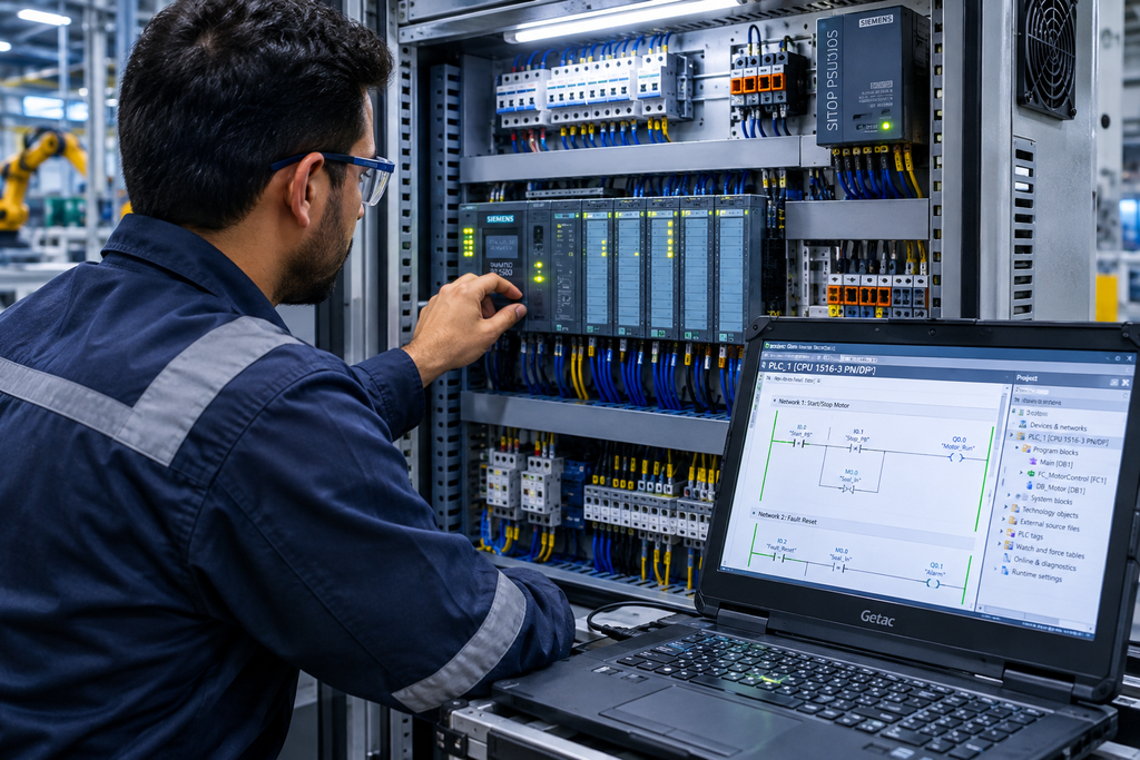
In modern industrial facilities—spanning from automated manufacturing plants and chemical processing refineries to water treatment facilities and power generation units—the entire operation relies on precise, high-speed, and reliable control systems. At the heart of this digital transformation is the Programmable Logic Controller (PLC).
Replacing antiquated, hardwired relay logic systems, PLCs provide the robust computational foundation needed to manage complex industrial machinery, ensure rigorous plant safety, and optimize continuous process loops. If you are an automation engineer, system integrator, plant manager, or technical student, understanding PLC hardware architecture, IEC 61131-3 programming languages, scan cycle execution, and system integration strategies is vital for long-term professional success.
1. Evolution and Core Hardware Architecture of Modern PLCs
To appreciate how modern control systems function, it is essential to look at how PLCs evolved and how their internal hardware is structured to withstand harsh industrial environments.
From Relay Logic to Microprocessor-Based Control
Before the invention of the PLC in the late 1960s, industrial automation relied on massive panels filled with thousands of electromechanical relays, timers, and counters. Whenever a manufacturing sequence needed modification, technicians had to manually rewire physical cables—a costly, time-consuming, and error-prone process. The introduction of the PLC allowed engineers to modify control logic via software without altering physical wiring.
The Internal Hardware Components
A standard industrial PLC consists of several core hardware subsystems working in unison:
- The Central Processing Unit (CPU): The brain of the PLC. It executes the user control program, manages memory allocation, and communicates with internal and external network devices.
- Memory Subsystem: Comprises RAM (Random Access Memory) for storing active variable states during program execution, and EEPROM/Flash ROM for permanent storage of the user application code.
- Power Supply Unit (PSU): Converts incoming AC or DC line voltages (e.g., 120V/230V AC or 24V DC) into stable, low-voltage DC rails (typically +5V and +24V) required by the processor and I/O modules.
- Input/Output (I/O) Sections: The bridge between the controller and the physical machinery. Discrete modules handle digital on/off signals (switches, pushbuttons, solenoid valves), while analog modules process continuous variables (4–20mA or 0–10V signals from pressure transmitters and thermocouples).
2. Understanding the PLC Scan Cycle Mechanics
One of the most crucial concepts for any automation programmer to master is the PLC Scan Cycle. Unlike standard high-level programming languages that execute sequentially from top to bottom continuously, a PLC operates in a strict, repetitive loop.
The 4 Phases of a Single Scan Cycle
- Phase 1: Input Scan: The CPU reads the physical state of all input terminals on the input modules and copies their statuses into a memory table known as the Input Image Table.
- Phase 2: Program Execution: The CPU reads the user control logic line by line (or rung by rung), evaluating Boolean expressions, calculating math algorithms, and updating the Output Image Table in memory based on the current Input Image state.
- Phase 3: Communications & Housekeeping: The CPU handles internal diagnostics, executes background system checks, and services communication requests from connected Human-Machine Interfaces (HMIs) or supervisory SCADA networks.
- Phase 4: Output Scan: The CPU takes the finalized data from the Output Image Table and physically updates the output modules, switching field devices (such as motor starters, indicator lamps, and control relays) on or off.
Understanding this sequence prevents common programming bugs, such as race conditions or unexpected timing anomalies in high-speed applications.
3. IEC 61131-3 Programming Languages: Choosing the Right Tool
The international standard IEC 61131-3 defines the syntax and semantics of programming languages used for industrial controllers. Mastering these languages allows engineers to select the most efficient structure for each specific automation task.
Comparative Overview of IEC 61131-3 Languages
| Programming Language | Description | Best Suited For |
| Ladder Logic (LD) | Graphical relay-equivalent language using electrical contact rails and coils. | Boolean interlocks, standard start/stop circuits, and technician-friendly troubleshooting. |
| Function Block Diagram (FBD) | Graphical block-oriented language where data flows between processing blocks. | Continuous process control loops, math calculations, and analog signal processing. |
| Structured Text (ST) | High-level text-based language resembling Pascal or C. | Complex algorithms, string manipulation, array handling, and advanced data processing. |
| Sequential Function Chart (SFC) | Step-transition flowchart structure dividing complex sequences into manageable states. | Batch processing, sequential machine control, and recipe management systems. |
4. Wiring, Signal Conditioning, and Panel Best Practices
Physical reliability in industrial automation is heavily dependent on proper electrical installation, grounding, and signal segregation.
- Sink vs. Source Wiring: Understanding current flow is critical when connecting DC sensors to PLC inputs. Sourcing inputs provide current out to the field device, while Sinking inputs receive current flowing from an external power source. Incorrect configuration can lead to damaged input cards or erratic signal states.
- Interposing Relays: To protect expensive PLC digital output cards from inductive kickbacks and high-current loads (such as heavy-duty contactors or motor starters), engineers use interposing control relays to isolate the PLC from high-power circuits.
- Electromagnetic Interference (EMI) Mitigation: Industrial control panels must separate high-voltage AC power cables from low-voltage shielded analog signal cables to prevent noise coupling and erratic sensor readings. Proper chassis grounding and panel bonding are mandatory for code compliance.
5. Industrial Networks and System Integration
Modern PLCs do not operate in isolation; they are integral nodes in expansive plant-wide industrial networks.
- Modbus RTU & TCP: Widely used serial and Ethernet protocols enabling seamless communication between legacy instruments, drives, and modern controllers.
- ProfiNet and EtherNet/IP: High-speed deterministic industrial Ethernet standards used to exchange real-time I/O data between controllers, remote I/O drops, and smart actuators.
- OPC UA Architecture: The industry standard for secure, platform-independent data exchange, allowing PLCs to securely transmit operational data directly to cloud historians, MES platforms, and enterprise digital twins.
6. Practical Checklist: PLC Panel Inspection & Commissioning Matrix
Use this practical field checklist during factory acceptance testing (FAT), site acceptance testing (SAT), or routine maintenance overhauls:
- [ ] Visual Hardware Inspection: Verify that all PLC racks, power supplies, CPU modules, and I/O cards are securely mounted and properly seated in their backplane slots.
- [ ] Power Supply Voltage Verification: Measure incoming voltage at the primary terminals and verify regulated 24V DC output rails prior to energizing I/O cards.
- [ ] Grounding Continuity Check: Confirm that all DIN rails, panel enclosures, and shielded cable drain wires are bonded to a dedicated clean earth ground bar.
- [ ] I/O Channel Force Test: Perform a point-to-point hardware check by forcing digital and analog channels via the programming software to verify field device wiring.
- [ ] E-Stop Safety Chain Validation: Physically test all Emergency Stop pushbuttons to ensure they drop out safety control circuits independently of PLC software logic.
- [ ] Backup and Version Control: Archive the final validated PLC program file, document checksum values, and store encrypted backup copies on secure plant servers.
7. Conclusion: Advancing Your Industrial Automation Career
Programmable Logic Controllers remain the indispensable backbone of modern heavy industry and smart manufacturing. Mastering PLC hardware architecture, understanding strict scan cycle timing, selecting the appropriate IEC 61131-3 programming language, and executing rigorous commissioning practices are essential skills for any elite automation engineer.
🚀 Accelerate Your Engineering Career with Free Documents Hub
Knowing how to program and commission automation systems is only half the battle; mastering modern industrial documentation, code compliance, and smart control frameworks is what sets top-tier engineers apart.
At Free Documents Hub, we offer specialized remote training programs covering industrial engineering design, PLC programming workflows, and technical documentation. Our programs are specifically designed to bridge the gap between academic theory and real-world shop-floor execution.
🛠️ Ready to elevate your technical credentials?